AKLLA A5 ITX CASE Discussion

survfate

Trash Compacter
Jul 30, 2020
36
33
With the A5, as the bottom end can be left open would a 320mm GPU fit just fine and maybe add some 15mm foot pads on it to raise it up a little bit?
no, but there are 2 kind of workaround.

1. do it like the way this guy fit his 3090:

2. flip the whole case and have your gpu poke out a little bit in the top and maybe 3d print a top hat for the extra.

I would just get the A5 Max tbh
 
  • Love
Reactions: SiKiaTriK

robbee

King of Cable Management
n3rdware
Bronze Supporter
Sep 24, 2016
855
1,335
Exciting times, just put my order in for this case! Didn't botter with the taobao maze and just communicated by mail with Aklla, which went suprisingly well. Their English is good, they respond very fast within their timezone and they invoiced through paypal so there is some form of customer protection.

Let's hope the product is as suprisingly good too! Should arrive in 7-10 days according to their representative.
 

robbee

King of Cable Management
n3rdware
Bronze Supporter
Sep 24, 2016
855
1,335
Update: the case has arrived! Got picked up by Fedex on the 10th in HK and was at my door in Belgium 4 days later, that was very quick. No import fees too so that was a nice surprise.

Didn't have a lot of time yet to build in it but overal it looks good. There are some tiny scratches and machining marks but they're all on the inside so that's fine. The tolerances and the machining are very good and those chamfered ventilation holes are really next level.

The finish is very nice too. The color is almost identical to my Macbook pro 'space grey' although it's a little bit more glossy. The only nitpick is that the front and back panels are a tiny bit more glossy than the sidepanels.

Some other things worth noting:
- The labels on the power button cables are now correct, looks like Aklla has used all their wrongly labelled buttons (HDD led was power button and power button was HDD led on most Aklla cases in the past)
- Case feet are a little disappointing, just some rubber pads you glue on. I'll 3d print or look for some better feet
- I definitely need an angled DP cable because there is not enough room for a straight one to make the bend
- The case didn't come with a manual or instructions so you'll spend some time figuring things out but that shouldn't be an issue for us SFF freaks

I'm gonna build a more detailed build log later on. Stay tuned!
 

survfate

Trash Compacter
Jul 30, 2020
36
33
- Case feet are a little disappointing, just some rubber pads you glue on. I'll 3d print or look for some better feet
they did officially sell varous aluminium feet (speaker feets) type for all of their cases, the sticky one is alway crap since the A4v2 days...


funklizard

Chassis Packer
Aug 16, 2017
16
10
Update: the case has arrived! Got picked up by Fedex on the 10th in HK and was at my door in Belgium 4 days later, that was very quick. No import fees too so that was a nice surprise.

Nice. We don't (typically) have to deal with import fees in the US; but my experience with shipping has been much, much slower.

I got my A5 Max a few weeks ago, downsizing from a Phanteks Evolv Shift (which is an extremely well made case for the money, but just way bigger than I wanted).

I am loving the A5 Max.

Didn't have a lot of time yet to build in it but overal it looks good. There are some tiny scratches and machining marks but they're all on the inside so that's fine. The tolerances and the machining are very good and those chamfered ventilation holes are really next level.

The finish is very nice too. The color is almost identical to my Macbook pro 'space grey' although it's a little bit more glossy. The only nitpick is that the front and back panels are a tiny bit more glossy than the sidepanels.

Mine has some minor imperfections in the finish on the back panel; but aside from that, it's awesome.

Some other things worth noting:
- The labels on the power button cables are now correct, looks like Aklla has used all their wrongly labelled buttons (HDD led was power button and power button was HDD led on most Aklla cases in the past)

Hah... I didn't know about that. Mine are labelled correctly, too.

- Case feet are a little disappointing, just some rubber pads you glue on. I'll 3d print or look for some better feet

That is a bummer. Mine came with nice padded feet that are attached with machine screws. They're either aluminum or very hard plastic.

Edit: After looking at the link that @survfate posted, I can report that my case included the type A feet pictured there.

- I definitely need an angled DP cable because there is not enough room for a straight one to make the bend

Yes, you do. (I was able to find one on Amazon.)

Once that's solved, you still might run into issues with USB-A connectors (if you plug any of those into the back). While mostly you can find lower-profile USB-A connectors these days, I've got a 10Gb cable (moderately hard to find with a USB-A connector) that is kind of a tight fit.

- The case didn't come with a manual or instructions so you'll spend some time figuring things out but that shouldn't be an issue for us SFF freaks

Yeah, this definitely upped the challenge level a bit; especially considering how configurable this case is. The posting on chiphell.com was invaluable; but I still have several screws whose role I have NFI about.

So, here's my baby:


Specs are:
  • ASRock Rack X570D4I-2T w/ 2x Noctua NF-A4x10 PWM fans
  • Ryzen 3950X w/ EVGA CLC 120 CL11 cooler w/ NF-A12x25 PWM fan
  • 4x Samsung M474A4G43MB1-CTD 32 GB DDR4-2666 ECC SODIMMs
  • Samsung 980 Pro 2 TB SSD
  • Radeon RX 5700 XT reference (other side)
  • Seasonic Focus SGX 650 power supply w/ CableMod cables
A few tips:
  • Motherboard goes in first; then attach the riser cable before you screw the other end of the riser cable onto the plate. You probably don't want to bother screwing the female end of the cable onto the plate until you've at least mostly installed the video card.
  • Avoid using an SFX-L power supply (like I did). There is some serious smooshing going on with the connectors going into the power supply. (The Seasonic flat cables that came with the unit actually fared better than the CableMod cables.)
My one complaint is that the bottom plate doesn't have any holes drilled for a 140mm fan/radiator.
 
Last edited:

Valantar

Shrink Ray Wielder
Jan 20, 2018
2,201
2,225
Nice. We don't (typically) have to deal with import fees in the US; but my experience with shipping has been much, much slower.

I got my A5 Max a few weeks ago, downsizing from a Phanteks Evolv Shift (which is an extremely well made case for the money, but just way bigger than I wanted).

I am loving the A5 Max.


Mine has some minor imperfections in the finish on the back panel; but aside from that, it's awesome.


Hah... I didn't know about that. Mine are labelled correctly, too.


That is a bummer. Mine came with nice padded feet that are attached with machine screws. They're either aluminum or very hard plastic.


Yes, you do. (I was able to find one on Amazon.)

Once that's solved, you still might run into issues with USB-A connectors (if you plug any of those into the back). While mostly you can find lower-profile USB-A connectors these days, I've got a 10Gb cable (moderately hard to find with a USB-A connector) that is kind of a tight fit.


Yeah, this definitely upped the challenge level a bit; especially considering how configurable this case is. The posting on chiphell.com was invaluable; but I still have several screws whose role I have NFI about.

So, here's my baby:


Specs are:
  • ASRock Rack X570D4I-2T w/ 2x Noctua NF-A4x10 PWM fans
  • Ryzen 3950X w/ EVGA CLC 120 CL11 cooler w/ NF-A12x25 PWM fan
  • 4x Samsung M474A4G43MB1-CTD 32 GB DDR4-2666 ECC SODIMMs
  • Samsung 980 Pro 2 TB SSD
  • Radeon RX 5700 XT reference (other side)
  • Seasonic Focus SGX 650 power supply w/ CableMod cables
A few tips:
  • Motherboard goes in first; then attach the riser cable before you screw the other end of the riser cable onto the plate. You probably don't want to bother screwing the female end of the cable onto the plate until you've at least mostly installed the video card.
  • Avoid using an SFX-L power supply (like I did). There is some serious smooshing going on with the connectors going into the power supply. (The Seasonic flat cables that came with the unit actually fared better than the CableMod cables.)
My one complaint is that the bottom plate doesn't have any holes drilled for a 140mm fan/radiator.
Nice build, but the angle of that 24-pin connector looks really worrying to me. Is there really that much force on it? That looks like it could damage something.
 

funklizard

Chassis Packer
Aug 16, 2017
16
10
Nice build, but the angle of that 24-pin connector looks really worrying to me. Is there really that much force on it? That looks like it could damage something.
There is virtually zero force on it. ;)

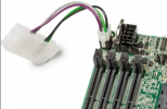
This motherboard doesn't actually have a 24-pin connector; it has a 4-pin power connector and the board comes with a 24-pin-to-4-pin adapter, which is itself about 10 cm long (including the connectors). The shortest 24-pin power connector that CableMod will make is 15 cm. So, what you're seeing there is how I have curled these two lengths and connectors around and slightly behind the EPS cable. (Where the 4-pin goes into the board is obscured by the cables in this pic.)

It would be lovely if I could find someone who'd build a custom cable that would go straight from the PSU to the 4-pin input on the motherboard; but after fishing for that for a little while and having no success, I gave up.
 

Valantar

Shrink Ray Wielder
Jan 20, 2018
2,201
2,225
There is virtually zero force on it. ;)

This motherboard doesn't actually have a 24-pin connector; it has a 4-pin power connector and the board comes with a 24-pin-to-4-pin adapter, which is itself about 10 cm long (including the connectors). The shortest 24-pin power connector that CableMod will make is 15 cm. So, what you're seeing there is how I have curled these two lengths and connectors around and slightly behind the EPS cable. (Where the 4-pin goes into the board is obscured by the cables in this pic.)

It would be lovely if I could find someone who'd build a custom cable that would go straight from the PSU to the 4-pin input on the motherboard; but after fishing for that for a little while and having no success, I gave up.
Ah, that makes sense :p

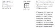
What's the pinout of that 4-pin? Is the adapter just straight wires, or does it do any type of voltage conversion PCB in-line? If it's just straight wires it should be pretty trivial to DIY an adapter - all you'd really need is a pin removal tool (whichever one you get, make sure it's good quality, as crap ones can bend easily), as long as you're okay with leaving four wires of the stock cable length. No cutting, no soldering, no crimping required.

Just mark the relevant wires on the 24-pin cable (I just make a tape "flag" on each wire and number/label them), detach these from the motherboard-side 24-pin connector, remove the unnecessary wires from the PSU-side 24-pin (or however many wires it has including voltage sense etc. - if any of the relevant lines have sense wires, leave them in place), depin the 4-pin end of your 24-to-4-pin adapter, and insert the labeled wires from the no-longer-24-pin cable into the correct sockets, taking care to insert them the correct way around (they shouldn't rotate at all once inserted). They should click into place and stay there securely. You'll be left with a bunch of spare wiring and some connectors, which you can keep if you ever want to reverse the process to use the PSU on a standard motherboard or use the 24-to-4 adapter with another PSU.

If you've never used a pin removal tool this might take half an hour, and having a multimeter on hand to test the voltage output of the resulting cable is always a good safety net, but overall it should be incredibly simple.
 

Mackan

Airflow Optimizer
Jun 2, 2016
302
160
Would be nice if they had black color. That is the only color I buy computer cases/stuff in.

Sorry, I meant the A3 CNC Max case. Mixed them up.
 

robbee

King of Cable Management
n3rdware
Bronze Supporter
Sep 24, 2016
855
1,335
I finished my build yesterday and got some more stuff to share. The main 'issue' i had is that is that i had to take off the case IO panel quite a few times because:

1. my motherboard has an integrated IO shield and couldn't be put in or taken out with the case panel in place
2. my GPU (Asus RTX 3080 TUF) only has 5mm spare room which wasn't enough to put it into place or taken it out with the panel into place

Once you get to know this limitation though, you quickly realise that you have to think some steps ahead before putting in the MB/GPU or just leave the panel detached until you're 100% ready.

I've got the spine in the 2.5 slot GPU position which is just about enough for my GPU. There's 1-2mm between the fans and the panel, which does cause some turbulence unfortunately. But that tight fit is just so satisfying. I've undervolted my card to .875v and let the temperature get up to 78C before really ramping up the fans. In games, this cools the GPU with the fans around 1200 RPM which doesn't create too much turbulence noise.

On the motherboard side, there is 74mm of CPU cooler clearance in this config. I'm using the Noctua NH-L12S which is perfect to keep my R5 3600 at bay while being very quiet.

My only gripe is that I'm still not convinced by the PSU placement but that's a detail. They could've just made a vertical hole in the back like they did for the horizontal placement of the PSU and then the power cord extension wouldn't be required.

Now I'm only waiting for the angled DP cable so I can place the case with IO on the bottom, that should decrease GPU thermals (and more importantly, turbulence noise) quite a bit.

I'll take some images this weekend.
 

Valantar

Shrink Ray Wielder
Jan 20, 2018
2,201
2,225
good explanation @Valantar

According to the manual it's just a simple adapter so it's not too difficult to mod this DIY and get rid of the 20 unnecessary ATX cables. The biggest challenge is not to break that pin removal tool. I've already damaged quite a few XD

View attachment 1331

View attachment 1332
Lol, yeah, I had one of those cheapo sets of pin removal tools initially (this style), and I believe the two-pronged one bent on the third or fourth pin, with one of the prongs breaking off entirely. I'm just glad I avoided stabbing my fingertip (it was pretty close!) as that seems like it would have been excruciatingly painful. My current spring-steel one (this one, which is really good) hasn't shown the slightest sign of wanting to bend even with really stubborn pins.
 
  • Like
Reactions: BaK

funklizard

Chassis Packer
Aug 16, 2017
16
10
Ah, that makes sense :p

What's the pinout of that 4-pin? Is the adapter just straight wires, or does it do any type of voltage conversion PCB in-line? If it's just straight wires it should be pretty trivial to DIY an adapter - all you'd really need is a pin removal tool (whichever one you get, make sure it's good quality, as crap ones can bend easily), as long as you're okay with leaving four wires of the stock cable length. No cutting, no soldering, no crimping required.

As @REVOCCASES noted, it's electrically trivial.

Thanks for the explanation. However, having never performed such surgery before, I've been a little reluctant to dive in.

If I do dive in, though, no half-measures: I'd cut the cable and crimp on new connectors.
 

BaK

King of Cable Management
Bronze Supporter
May 17, 2016
930
931
Lol, yeah, I had one of those cheapo sets of pin removal tools initially (this style), and I believe the two-pronged one bent on the third or fourth pin, with one of the prongs breaking off entirely. I'm just glad I avoided stabbing my fingertip (it was pretty close!) as that seems like it would have been excruciatingly painful. My current spring-steel one (this one, which is really good) hasn't shown the slightest sign of wanting to bend even with really stubborn pins.
Good to hear there is a removal tool that works, thx for the link.
I've never been statisfied with the ones I tried, so I am now using staples, the bigger sturdy ones.
First I made one staple flat, then bent it in the middle at right angle, and to protect my fingers put some heatshrink on one half. So that you can push on the heatshrink part to insert the naked one into the connector. Two staples like that and you are good to go.
It is a little tricky to apply pressure on both the staples while pulling on the wire, but once you get familiar with it it works fine!
 
  • Like
Reactions: Valantar

dannycpham

Trash Compacter
Mar 25, 2019
54
74
Nice. We don't (typically) have to deal with import fees in the US; but my experience with shipping has been much, much slower.

I got my A5 Max a few weeks ago, downsizing from a Phanteks Evolv Shift (which is an extremely well made case for the money, but just way bigger than I wanted).

I am loving the A5 Max.


Mine has some minor imperfections in the finish on the back panel; but aside from that, it's awesome.


Hah... I didn't know about that. Mine are labelled correctly, too.


That is a bummer. Mine came with nice padded feet that are attached with machine screws. They're either aluminum or very hard plastic.

Edit: After looking at the link that @survfate posted, I can report that my case included the type A feet pictured there.


Yes, you do. (I was able to find one on Amazon.)

Once that's solved, you still might run into issues with USB-A connectors (if you plug any of those into the back). While mostly you can find lower-profile USB-A connectors these days, I've got a 10Gb cable (moderately hard to find with a USB-A connector) that is kind of a tight fit.


Yeah, this definitely upped the challenge level a bit; especially considering how configurable this case is. The posting on chiphell.com was invaluable; but I still have several screws whose role I have NFI about.

So, here's my baby:


Specs are:
  • ASRock Rack X570D4I-2T w/ 2x Noctua NF-A4x10 PWM fans
  • Ryzen 3950X w/ EVGA CLC 120 CL11 cooler w/ NF-A12x25 PWM fan
  • 4x Samsung M474A4G43MB1-CTD 32 GB DDR4-2666 ECC SODIMMs
  • Samsung 980 Pro 2 TB SSD
  • Radeon RX 5700 XT reference (other side)
  • Seasonic Focus SGX 650 power supply w/ CableMod cables
A few tips:
  • Motherboard goes in first; then attach the riser cable before you screw the other end of the riser cable onto the plate. You probably don't want to bother screwing the female end of the cable onto the plate until you've at least mostly installed the video card.
  • Avoid using an SFX-L power supply (like I did). There is some serious smooshing going on with the connectors going into the power supply. (The Seasonic flat cables that came with the unit actually fared better than the CableMod cables.)
My one complaint is that the bottom plate doesn't have any holes drilled for a 140mm fan/radiator.

Hello!
Is the 120mm water cooler actually attached to the bottom of the plate?

Would it be possible to reorient the whole build so the 120mm exhausts air out through the top side instead of intaking air from the bottom.
 

funklizard

Chassis Packer
Aug 16, 2017
16
10
Hello!
Is the 120mm water cooler actually attached to the bottom of the plate?
Yes. (Screws go through the bottom plate through the fan and into the radiator.)
Would it be possible to reorient the whole build so the 120mm exhausts air out through the top side instead of intaking air from the bottom.
I think so.

You can definitely change the orientation of this case. Though normally you'd use the perforated plate on top; you might need to put the bottom plate up top (unless the perforations in the top plate happen to line up with the screw holes you need; not sure about that).

Edit: A couple more notes... Most 140mm radiators will fit in this case. However, there are no holes in the 140mm fan/radiator screw positions. (I have plans; I just need to locate a drill press.)

Also, a non-blower video card might fare better with the case inverted; however, I suspect you'll get better CPU cooling by blowing cool outside air over the radiator.
 
Last edited:

survfate

Trash Compacter
Jul 30, 2020
36
33
Edit: A couple more notes... Most 140mm radiators will fit in this case. However, there are no holes in the 140mm fan/radiator screw positions. (I have plans; I just need to locate a drill press.)
could a 3d print 120 to 140mm adapter possibly work so you dont have to drill the case?