This thread acts as the main thread about the XWORKS 70 xFrame SFF chassis.
We will try to answer/discuss and provide as much information as possible on the choices made and the ongoing evolution of the xFrame series.
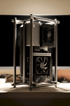
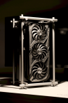
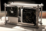
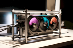
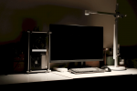
- Bring the hardware to the forefront and keep it tidy
- Standard Compatibility : Mini-ITX + SFX + most Air Coolers + Large Graphic Cards, 2.5" storage.
- (For now) this is an Air-Cooling focused case
- PCI-E 4.0 x16 riser
- XWORKS 70 xFrame chassis incl. all necessary screws & tool to assemble
- Premium Express Shipping Service Worldwide (Some remote locations might have a surcharge) - For all orders on XWORKS.store.
Aesthetics always had a strong influence, especially in the xFrame Project. Removing the sharp corners of a boxed case and aiming for lightness/openness has been discussed countless times. Aluminum was a no-brainer as a choice of material.
Designing the main body "inner-frame"
The main body ("inner-frame") that house all the hardware, supported by a light "frame" made of rounded aluminum rods was a clear winner approach for the xFrame Project.
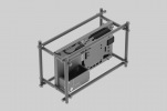
The "inner-frame" design took influence and learnings from the first XWORKS SFF case: The XWORKS X32. Some of the ideas and tweaks that could not be implemented on the X32 have been on the 70 xFrame.
Some example of evolution we could implement:
- The hooks for cable ties are directly cut out in the inner-frame but are still hidden behind the motherboard or other components
- Extra space for Storage connectors for easier assembly/maintenance
- More obvious cable routing inside the main "inner-frame"
- Reducing the number of different screws (where possible)
- Simplifying the assembly steps (not reducing in number but in making it more convenient to assemble)
- Allowing for greater modification (more on this later)
- Accepting regular-size/large GPUs (not only limited to SFF-focused graphic cards)
It might not look like it at first sight but the "inner-frame" went through quite a lot of iterations. Some ideas were looking interesting on paper/when discussed but really failed to deliver any added-value for the end-user when we tested them or flat-out was a nightmare to manufacture.
In parallel to the inner-frame becoming more and more polished, the more visible part was also taking a good share of our brain's time.
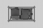
Routing and hiding cable always was on our mind. The X32 had a completely hidden PSU (because most of the Flex PSU are... ugly.), this was not a concern on the 70 xFrame as it uses SFX PSU. The SFX PSU market is mature enough to have a proper selection of modular & good looking units.
Still, a modular PSU with half the cable plugged or "somewhat" nice cable going to a "hole" in the inner-frame is not really a good-enough-looking option. This is how the cable cover was created, and doubles as the only-place where branding is visible, along-side with the power-button.
The GPU Support bracket uses the same concept as the one on the X32 but pushes the iterations and thinking much further. Accommodating a large GPU also required tweaks to support the weight and still allow for easy installation/maintenance.
Screw this!
Finally, the choice of screws has been thoroughly discussed (or should I say argued?) and the outcome is simple :
- Any directly visible screws will be CD-pattern (aka "good-looking screws")
- Any other screws will be black (aka "not visble")
- Try to re-use as many of the same type of screw as possible (not without challenges!)
Due to structural requirements, length and hard limitations: there are still a bunch of different screws types but they are all clearly labeled (in the screw-box) and identified in the assembly guide.
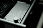
This gives a broad view of the mindset & concept-thinking that went into the design of the inner-frame. Let's tackle the visible part!
The rods concept
While the iterations in the inner-frame were going nuts, using rods for the frame support came with its slew of challenges and questioning.
The mindset is to deliver a system that is more like a piece of art and breaking the status-quo rather than a traditional computer case. For this, we tend to apply the same reasoning : What emotions do we feel / want to express & how can we make it aesthetically pleasing (still very subjective anyway).
It was quite a challenge to stick to the mindset of "deliver a product that is clean, polished and aesthetically pleasing" and still address the underlying challenges to ensure the case holds together and is easy to assemble. We need to make sure that the case will not wobble once assembled. (spoiler alert : it is stable AF )
)
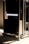
Why a rod-frame? Rods are used in the professional photography world to extend a base system with accessories. This is part of the mindset behind the xFrame series as well. So looking into the photography world was a natural path.
Let's say that it was a rough-path and many iterations and prototypes later we found a way to balance the target idea with the production complexity/capabilities.
Something we learned during this 70 xFrame prototyping phase was that some ideas are great, look great, feel great but are extremely difficult to manufacture or cannot be manufactured reliably enough for an acceptable price. (Spoiler alert, manufacturing is hard & painful...)
The XWORKS 70 xFrame uses a joint of 3 rods, tightly attached together with no visible screws (from the outside perspective). Each rods play a role in distributing the weight and support of the inner-frame.
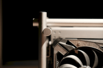
The inner-frame can attach in 4 positions to accomodate for larger CPU Coolers or larger Graphic Cards/accessories.
Flatpacking
Finally the box itself took some time and iterations to be completed. In the end, it all fits nicely and in a smaller footprint than a regular case.
The case comes in a flat-pack box and ready-to-be assembled.
This helps a lot on storaged space, material quantity / usage as well as shipping logistics in general.
ATX 24-pin for Motherboard
Official XWORKS Site : https://xworks.store/
XWORKS 70 xFrame Product Page : https://xworks.store/products/xworks-70-xframe-small-form-factor-open-air-case
XWORKS 70 xFrame Assembly / Build Guide : https://xworks.store/pages/70xframe-manual
We will try to answer/discuss and provide as much information as possible on the choices made and the ongoing evolution of the xFrame series.
XWORKS 70 xFrame
"The XWORKS 70 xFrame is a small-form-factor open air A4-type computer case crafted for those who appreciate aesthetics as much as performance."


Design Goals
- Break from more traditional boxed/closed design- Bring the hardware to the forefront and keep it tidy
- Standard Compatibility : Mini-ITX + SFX + most Air Coolers + Large Graphic Cards, 2.5" storage.
- (For now) this is an Air-Cooling focused case
Availability & distribution
The XWORKS 70 xFrame comes with:- PCI-E 4.0 x16 riser
- XWORKS 70 xFrame chassis incl. all necessary screws & tool to assemble
- Premium Express Shipping Service Worldwide (Some remote locations might have a surcharge) - For all orders on XWORKS.store.
The genesis behind the 70 xFrame
It started about 2.5 years ago, when the XWORKS designer team wanted to focus on an A4 format case. But it was clear that the "open-air" concept would still be a priority.Aesthetics always had a strong influence, especially in the xFrame Project. Removing the sharp corners of a boxed case and aiming for lightness/openness has been discussed countless times. Aluminum was a no-brainer as a choice of material.
Designing the main body "inner-frame"
The main body ("inner-frame") that house all the hardware, supported by a light "frame" made of rounded aluminum rods was a clear winner approach for the xFrame Project.

The "inner-frame" design took influence and learnings from the first XWORKS SFF case: The XWORKS X32. Some of the ideas and tweaks that could not be implemented on the X32 have been on the 70 xFrame.
Some example of evolution we could implement:
- The hooks for cable ties are directly cut out in the inner-frame but are still hidden behind the motherboard or other components
- Extra space for Storage connectors for easier assembly/maintenance
- More obvious cable routing inside the main "inner-frame"
- Reducing the number of different screws (where possible)
- Simplifying the assembly steps (not reducing in number but in making it more convenient to assemble)
- Allowing for greater modification (more on this later)
- Accepting regular-size/large GPUs (not only limited to SFF-focused graphic cards)
It might not look like it at first sight but the "inner-frame" went through quite a lot of iterations. Some ideas were looking interesting on paper/when discussed but really failed to deliver any added-value for the end-user when we tested them or flat-out was a nightmare to manufacture.
In parallel to the inner-frame becoming more and more polished, the more visible part was also taking a good share of our brain's time.

Routing and hiding cable always was on our mind. The X32 had a completely hidden PSU (because most of the Flex PSU are... ugly.), this was not a concern on the 70 xFrame as it uses SFX PSU. The SFX PSU market is mature enough to have a proper selection of modular & good looking units.
Still, a modular PSU with half the cable plugged or "somewhat" nice cable going to a "hole" in the inner-frame is not really a good-enough-looking option. This is how the cable cover was created, and doubles as the only-place where branding is visible, along-side with the power-button.
The GPU Support bracket uses the same concept as the one on the X32 but pushes the iterations and thinking much further. Accommodating a large GPU also required tweaks to support the weight and still allow for easy installation/maintenance.
Screw this!
Finally, the choice of screws has been thoroughly discussed (or should I say argued?) and the outcome is simple :
- Any directly visible screws will be CD-pattern (aka "good-looking screws")
- Any other screws will be black (aka "not visble")
- Try to re-use as many of the same type of screw as possible (not without challenges!)
Due to structural requirements, length and hard limitations: there are still a bunch of different screws types but they are all clearly labeled (in the screw-box) and identified in the assembly guide.

This gives a broad view of the mindset & concept-thinking that went into the design of the inner-frame. Let's tackle the visible part!
The rods concept
While the iterations in the inner-frame were going nuts, using rods for the frame support came with its slew of challenges and questioning.
The mindset is to deliver a system that is more like a piece of art and breaking the status-quo rather than a traditional computer case. For this, we tend to apply the same reasoning : What emotions do we feel / want to express & how can we make it aesthetically pleasing (still very subjective anyway).
It was quite a challenge to stick to the mindset of "deliver a product that is clean, polished and aesthetically pleasing" and still address the underlying challenges to ensure the case holds together and is easy to assemble. We need to make sure that the case will not wobble once assembled. (spoiler alert : it is stable AF

Why a rod-frame? Rods are used in the professional photography world to extend a base system with accessories. This is part of the mindset behind the xFrame series as well. So looking into the photography world was a natural path.
Let's say that it was a rough-path and many iterations and prototypes later we found a way to balance the target idea with the production complexity/capabilities.
Something we learned during this 70 xFrame prototyping phase was that some ideas are great, look great, feel great but are extremely difficult to manufacture or cannot be manufactured reliably enough for an acceptable price. (Spoiler alert, manufacturing is hard & painful...)
The XWORKS 70 xFrame uses a joint of 3 rods, tightly attached together with no visible screws (from the outside perspective). Each rods play a role in distributing the weight and support of the inner-frame.

The inner-frame can attach in 4 positions to accomodate for larger CPU Coolers or larger Graphic Cards/accessories.
Flatpacking
Finally the box itself took some time and iterations to be completed. In the end, it all fits nicely and in a smaller footprint than a regular case.
The case comes in a flat-pack box and ready-to-be assembled.
This helps a lot on storaged space, material quantity / usage as well as shipping logistics in general.
PRODUCT SPECIFICATION
Technical Specs- Chassis weight: 2.5kg
- Chassis dimension: 387x228x185mm
- Material: 6061-T6 aluminum alloy
- Color: Space Gray
- Finish: anodized and fine-grit sandblasted
- Shipping weight: 3.1kg
HARDWARE COMPATIBILITY
Components- Motherboard: Mini-ITX
- PSU: SFX (hidden power extension cable provided)
- Storage: 2x 2.5" HDD/SSD, 7mm thick (fits inside the main body)
- Compatibility of each inner frame positions:
- Position 1: unlimited length, maximum 3-slot
- Position 1-4: ≤325mm in length, maximum 4-slot
- The chassis supports maximum 3-slot GPU bracket
- If the thickness of GPU body is less than the designed thickness of current inner frame position, GPU can protrude out of the chassis, and thus have no length limitations:
- Position 1: designed thickness - 3 slot unlimited length
- Position 2: designed thickness - 3 slot
- Position 3: designed thickness - 2.6 slot
- Position 4: designed thickness - 2.2 slot
- For example, a 2-slot card with inner frame at Position 3 can protrude out, thus does not have length limitation of ≤325mm
- Recommended air cooler height for each inner frame positions:
- Position 1: ≤40mm
- Position 2: ≤53mm
- Position 3: ≤60mm
- Position 4: ≤70mm
- Coolers within the above size falls inside the case envelope
- Fan thickness included for the above calculation
CUSTOM CABLES PARAMETERS (OPTIONAL)
The following specifications are recommended for custom-made cables. All the lengths mentioned exclude the connector housing.ATX 24-pin for Motherboard
- 24cm
- Latches on the same side when laid flat
- 40cm
- Latches on the same side when laid flat
- 23cm
- Latches on the opposite side when laid flat
- Number of cables required vary per graphic card
- 35cm + 10.5cm for the second connector
- Use flat connectors & straight cable-entry
- Recommended to use thin silicone wire (≥18 AWG)
- ≥20cm
- Straight connector must be used at the HDD/SSD side
- Right-angled or straight connector can be used at the motherboard side
- Tested compatible by the community :
- Silicone cable with braided plastic
- We recommend the use of modular power supply for ease of installation
Official XWORKS Site : https://xworks.store/
XWORKS 70 xFrame Product Page : https://xworks.store/products/xworks-70-xframe-small-form-factor-open-air-case
XWORKS 70 xFrame Assembly / Build Guide : https://xworks.store/pages/70xframe-manual
