• Save 15% on ALL SFF Network merch, until Dec 31st! Use code SFF2024 at checkout. Click here!

Power Supply FSP FSP500-30AS Modular Flex PSU from GEEEK, anyone have one?

milesvw

SFF Lingo Aficionado
Dec 20, 2022
137
99
I'm not familiar with the Xbox Powerbrick but yes it looks like it has the exact wires the j-hack is looking for (5vsb, ps on, and multiple 12v and ground). The only issue with the j-hack module is that it seems to be in back order, no clear ETA on what it would be available.
I need to double check the Xbox brick, I'm not sure if the 5VSB disappears when it switches on. Xbox360 supplies are much the same and are available in higher wattages for some of the earlier models.

I have a couple PicoPsu clones, I need to see if I can backfeed them with 5VSB, or cut their 5VSB and make my own JHack like device. I would much prefer wiring direct from PSU to CPU and PCIe power, but the JHack seems to be tailor made (I can always run power in both sides to make it more stable).

Still looking for a Pinout on the NUC9 Extreme baseboard. Or even a good picture of the back of the PCB so I can make some guesses. 10 pins, presumably 4 ground, 5VSB, PWOK? Then 2x 3.3v and 2x 12v? The 3.3v is 14A, so it can't be a single wire.

There is a peek inside the PSU here: https://wccftech.com/intel-ghost-canyon-nuc-element-pc-review-leaked/
 
Last edited:
  • Like
Reactions: dukedevil0

dukedevil0

Chassis Packer
Jan 18, 2024
13
6
I need to double check the Xbox brick, I'm not sure if the 5VSB disappears when it switches on. Xbox360 supplies are much the same and are available in higher wattages for some of the earlier models.

I have a couple PicoPsu clones, I need to see if I can backfeed them with 5VSB, or cut their 5VSB and make my own JHack like device. I would much prefer wiring direct from PSU to CPU and PCIe power, but the JHack seems to be tailor made (I can always run power in both sides to make it more stable).

Still looking for a Pinout on the NUC9 Extreme baseboard. Or even a good picture of the back of the PCB so I can make some guesses. 10 pins, presumably 4 ground, 5VSB, PWOK? Then 2x 3.3v and 2x 12v? The 3.3v is 14A, so it can't be a single wire.

There is a peek inside the PSU here: https://wccftech.com/intel-ghost-canyon-nuc-element-pc-review-leaked/
Great find on that internal photo inside the FSP power supply! I'll be opening mine up when it arrives to look deeper inside.

So I did a little more digging and research (ok way too much research actually...)

I discovered there's another chassis option for the NUC9 Extreme compute element, which is the Cooler Master NC100. It comes with a case + PSU combo + slightly different baseboard, but still appears to use the same 10-pin connector on the baseboard as the Intel version. The PSU it uses is a Cooler Master V650 SFX Gold modular power supply. It uses a custom modular cable from the 10P + 18P connectors on the PSU side to the 10-pin BBWC1B connector on the baseboard. Reviewing some photos and videos, I was able to see which pins are present on the 10P + 18P side, and compared them to the pinout diagram of that PSU. Below is what I determined is going to the 10-pin BBWC1B connector. I have not been able to clearly figure out which pin is which on the 10-pin BBWC1B cable connector side yet.

Green highlight were pins found visually. Appears to be 13 total pins/wires on PSU side, with 3 of those being sense wires, which I assume those 3 are double wires into a single pin on the 10-pin BBWC1B connector. That leaves 10-pins for the connector on the baseboard side.

It seems the 10-pins should be 12v, 12v + sense, 3.3v, 3.3v + sense, GND, GND, GND, GND + sense, PS-ON, 5vsb.

So it's missing the Power Good/PW-OK signal?


Another helpful pinout diagram of the Cooler Master PSU, with pin numbers identified:

Helpful reference videos I used for the NC100 chassis/viewing the modular cable pins that were present:

Also, here are some pictures of the baseboards and 10-pin BBWC1B connectors in case these can help answer any questions:
https://www.kitguru.net/wp-content/uploads/2020/05/Baseboard-3.jpg
O1CN01cd7ibH1F81WVz7P2C_!!53-fleamarket.heic_468x468Q75.jpg (350×468) (alicdn.com) (backside of baseboard)

Hope this all is helpful and gets the discussion further along!
 

milesvw

SFF Lingo Aficionado
Dec 20, 2022
137
99
What I found on the 10 pin.

Also an 8 Pin standard ATX CPU? (Haven't checked it), and 2x 6+2 Pin for GPU. And a 2.54mm 4 pin+key. One pin of that is Ground, Assuming the rest are auxiliary signals, fan/temp/PWOk maybe? No sign of a 5v. Maybe the 3.3v daughter board.is swapped for a 3.3v+5v one? Would work really well as an eGPU, PicoPSU, auxiliary GPU power though.


No room for 5v 🫤, but plenty of beefy 12v 😆


Last edited:

milesvw

SFF Lingo Aficionado
Dec 20, 2022
137
99
Looking into the 10pin from the connector side with the clip on top:

_________Latch__________
3.3v Gnd PWOn Gnd Gnd
3.3v Gnd 5Vsb 12v 12v
________________________

No room inside or any solder points for 5v. I assume they either added a DC-DC 5v board, or replaced the 3.3v board with one that can make both 3.3v and 5v.

I think my Pico unit is a Pico Box 200w. I do have a few of the aluminum cased 150w DC-DC buck converters (the $10-15 sort). Still on the fence.
 
  • Like
Reactions: dukedevil0

dukedevil0

Chassis Packer
Jan 18, 2024
13
6
I just probed with a multimeter and discovered that there is in fact 5V present! And no, I’m not talking about the 5Vsb!

That small DC-DC board on the top takes a 12V input and converts to both 3.3V and 5V. It’s just that only 3.3V is labeled/hooked up to any wiring. I’m not sure if there is any decent place for the 5V output to be wired yet.
 

milesvw

SFF Lingo Aficionado
Dec 20, 2022
137
99
Sorry I have a message with pictures, but it is held up in moderation. I don't doubt there is 5v, but is it from power transistors or just for the control side of the 3.3v power?.

I'm only seeing 2 6.3v caps and a 16v cap under the 3.3v board. The 6.3v are next to the 3.3 out, and the 16.3 is nex to the 12v 'input' I need to investigate further. There are only 4 mosfets, and with the high rating of the 3.3v rail I assumed they were 2 pairs making 3.3v
 
Last edited:

dukedevil0

Chassis Packer
Jan 18, 2024
13
6
Here is the DC-DC controller chip on that daughter board.
APW7159.pdf

Here is the Typical Application Circuit in that PDF. It's showing nearly exactly what it's actually doing in this PSU.


You can see there are two separate outputs via two inductors shown in this circuit (L1 and L2). You can visually see the inductors on the underside of the board in the PSU.


I've labeled inductor L1 in the photo. I checked positive on the circled pins of that inductor going through the board, and negative to the main ground on this board. It reads 5V when the PSU is on, 0V when PSU is off!
 
Last edited:

milesvw

SFF Lingo Aficionado
Dec 20, 2022
137
99
Here is the DC-DC controller chip on that daughter board.

....

I've labeled inductor L1 in the below photo. I checked positive on the circled pins of that inductor going through the board, and negative to the main ground on this board. It reads 5V when the PSU is on, 0V when PSU is off!

I see. The two diodes near where you circled feed the 5Vsb, but prevent the 5Vsb from coming back into the circuit. Makes sense if you want to pump up the 5Vsb rail while PSU is on.

I would say the best place to tap the 5v power is the flat copper area there between R119 and the inductor you circled. That MOSFET is a 50A 060N03L, seems legit.
 

milesvw

SFF Lingo Aficionado
Dec 20, 2022
137
99
I guess my current (pun intended) plan is to de-pin the 3.3v and their ground wires from the 10-pin, and replace them with a 24-pin from a blown Apevia Flex PSU and solder to 3.3v, 5v and ground.

Then a female adapter to pick up the 12v, 5vSB and PW_ON from the 10(now 6)pin.

This keeps any soldering to the little auxiliary board, and reduces disassmbly.
 
  • Like
Reactions: vinnyoflegend

dukedevil0

Chassis Packer
Jan 18, 2024
13
6
I guess my current (pun intended) plan is to de-pin the 3.3v and their ground wires from the 10-pin, and replace them with a 24-pin from a blown Apevia Flex PSU and solder to 3.3v, 5v and ground.

Then a female adapter to pick up the 12v, 5vSB and PW_ON from the 10(now 6)pin.

This keeps any soldering to the little auxiliary board, and reduces disassmbly.
Why de-pin some and use an adapter for others? Wouldn’t it be easier to remove the pins for 12v, 5vSB and PW_ON from the 10-pin and pop them into the new 24-pin connector?

Do we need to worry about the missing Power Good/Power OK pin at all?

I’m very curious to know the solution they used in that GEEEK / Taobao modular version. I don’t suppose someone that has it and is comfortable enough to open it up and snap a few pictures?? @rcodi maybe?

Tempted to pick up something like this and make our own modular version.
https://www.aliexpress.us/item/3256801127647593.html
 
Last edited:

vinnyoflegend

Average Stuffer
Mar 18, 2022
77
39
Do we need to worry about the missing Power Good/Power OK pin at all?

Seems to be lots of interesting takes on this, apparently the motherboard just needs this to be +5v high, and some "bad"/"cheap" PSUs may tie it to an output line to achieve this if they aren't actually monitoring for good/stable rails. I could see it being bad to tie to 5vsb, but I would expect even with a monitoring circuit, it would still ultimately come out of the regular +5vdc.

ref:
 

dukedevil0

Chassis Packer
Jan 18, 2024
13
6
Seems to be lots of interesting takes on this, apparently the motherboard just needs this to be +5v high, and some "bad"/"cheap" PSUs may tie it to an output line to achieve this if they aren't actually monitoring for good/stable rails. I could see it being bad to tie to 5vsb, but I would expect even with a monitoring circuit, it would still ultimately come out of the regular +5vdc.

ref:
I'm betting if we dig deeper into this PSU that we'll find the supervisor IC chip. I have to think it would include a Power-OK/Power-Good signal, that we could solder up a wire to that runs to the 24-pin connector....but the question is whether it will be worth the hassle vs. the risk of just connecting to the normal 5v rail.
 
Last edited:

milesvw

SFF Lingo Aficionado
Dec 20, 2022
137
99
Why de-pin some and use an adapter for others? Wouldn’t it be easier to remove the pins for 12v, 5vSB and PW_ON from the 10-pin and pop them into the new 24-pin connector?
Because the ground and 3.3v all need to be doubled, since I'm crimping new wires. And I may want to use this in an eGPU or "12V only" with some kind of PicoPSU

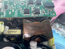
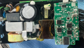
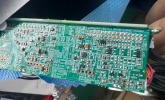
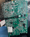
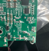
@dukedevil0 - I have it open but I don't really know what I'm looking for, here's some quick pics.
Thanks, it seems they added 5v right where we thought. They did add an extra Capacitor and some other lines.

I adapted it today, it ran a motherboard just fine, granted a cheesy ITX with embedded Celeron 847.


I used a terminal crimp set from Amazon, "Gikfun 4.2mm 18-24 AWG Wire Connectors" (B09BYT76NG or B09BNB86NR) and an Iwiss crimper 1424A (Amazon B01M1YK5FM) , but I had to grind it down a bit so it wouldn't destroy the pins:


dukedevil0

Chassis Packer
Jan 18, 2024
13
6
Ok that’s awesome! Great job. Super happy to see you’ve got it working.

A few questions:
1) Did you just use 5V or 5Vsb for the Power Good pin or…?
2) Were the two red 5v wires the only soldering you did?
3) Did you just double/triple wire at certain pins at the adapter connectors as needed? ie. It looks like the two red 5v wires you soldered then went into five wires out of the adapter, correct? And similar done at the 10-pin adapter for the additional ground and 3.3v pins as needed?
 
Last edited:

vinnyoflegend

Average Stuffer
Mar 18, 2022
77
39
It's just slightly out of view in that picture :D we need to see the other side. Doesn't look like anything is there from the angle we have, so I'm also curious how it's working.