Prototype BASALT - a 9L vertical case that supports long 3 slot graphics card

robbee

King of Cable Management
Original poster
n3rdware
Bronze Supporter
Sep 24, 2016
855
1,335
Hello everyone,

I want to present a new concept that I've been working on. It builds on the awesome work of @Colinreay MK2 that he was so nice to open source. I initially wanted to build his exact case, but the lack of larger graphics card support bothered me a bit, especially after the latest generation of cards was introduced. So I went to the drawing table and altered the design so it could house most of the current cards.

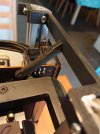
The concept and design language stay the same: 2020 rounded aluminium extusions, laser cut panels and 3d printer parts. I changed the orientation of the graphics card to vertical while having the motherboard IO remain at the back of the case, similar to how the Velka 7 does. The only difference is that the parts are layed out so that the riser only needs a single bend and the case is quite a bit higher.

Without further ado, let's see how the case will actually look:


As for the hardware support:
- 47mm CPU cooler clearance
- SFX(L) PSU
- GPU thickness up to 60mm (3 slots) thick, as long as it has 1 or 2 slot PCI bracket
- GPU length limited to 325mm without top fan, 321mm with 15mm top fan, 311mm with 25mm top fan
- GPU height up to 150mm and an extra 16mm for power connectors
- Top mounted 120mm fan
- Up to 2 2.5inch drives up to 9mm thick

Currently, I've collected most hardware and I've been printing some of the parts already. I'm still waiting for the extrusions and my laser cutter to arrive, which can be any day now.
 
Last edited:

robbee

King of Cable Management
Original poster
n3rdware
Bronze Supporter
Sep 24, 2016
855
1,335
hey robbe where will be the gpu cables ? routed to the bottom? btw looks very nice 👍

Yes, good question, I'll use very short extensions similar to Velka 5 and 7. You can see them highlighted in this screenshot (bottom of the case)

1610143093963.png

And the back of the case:

1610143134449.png
 

REVOCCASES

Shrink Ray Wielder
REVOCCASES
Silver Supporter
Apr 2, 2020
2,057
3,331
www.revoccases.com
Nice to see more vertical case concepts here, especially if DIY friendly.

The layout and dimensions reminding me a bit of my vertical MID2, but flipped, which makes it perfect for some air cooled build instead of the AIO I am using.

Did you already find some suitable riser cable? I tested quite a few before finding one which could be bend/folded flat enough.

Looking forward to the final build. 👍
 
Last edited:

robbee

King of Cable Management
Original poster
n3rdware
Bronze Supporter
Sep 24, 2016
855
1,335
Nice to see more vertical case concepts here, especially if DIY friendly.

The layout and dimensions reminding me a bit of my vertical MID2, but flipped, which makes it perfect for some air cooled build instead of the AIO I am using.

Did you already find some suitable riser cable? I tested quite a few before finding one which could be bend/folded flat enough.

Looking forward to the final build. 👍

I've been testing multiple risers and I have decided to go with the Hdplex silicon riser. It is super thin and can basically be folded at a 0mm radius. There is only about 5mm clearance for the bend so I needed the thinnest riser possible.
 
Last edited:
  • Like
Reactions: REVOCCASES

maibol

Cable Smoosher
Dec 6, 2020
12
1
Are you planing on sale this one ? or this is just a hobby for you to learn and having fun doing new stuff ?
 

robbee

King of Cable Management
Original poster
n3rdware
Bronze Supporter
Sep 24, 2016
855
1,335
Are you planing on sale this one ? or this is just a hobby for you to learn and having fun doing new stuff ?

I'll open source the design once the case is completed and might build kits for people who aren't familiar with printing/laster cutting their own parts. It'll largely depend on the interest in this case.
 

maibol

Cable Smoosher
Dec 6, 2020
12
1
I'll open source the design once the case is completed and might build kits for people who aren't familiar with printing/laster cutting their own parts. It'll largely depend on the interest in this case.
That's nice i'll love to see what you can accomplish with this one 👍 ........been checking around the forum and you guys do a great job ...... i like this new wave of vertical cases and your idea is a nice one small footprint and hopefully running cool
 

griever

Average Stuffer
Apr 30, 2019
59
14
This is great! Right now there doesn’t seem to be enough vertical sandwiches that don’t have some unfortunate I/O or VGA output compromise, much less supports 3-slot GPU.

I like the addition of the top exhaust fan.
the button in the middle is a bit distracting to the otherwise beautiful aesthetic, though.

If you market or open source the design I’d definitely use it. Currently my use case is me and my two sons consistently game together and move our rigs nearly every day. My case is a Velka 3 (which I wish I could replace) but they use Meshify C and those cases are too large and bulky for their small frames.

keep up the good work!
 

robbee

King of Cable Management
Original poster
n3rdware
Bronze Supporter
Sep 24, 2016
855
1,335
This is great! Right now there doesn’t seem to be enough vertical sandwiches that don’t have some unfortunate I/O or VGA output compromise, much less supports 3-slot GPU.

I like the addition of the top exhaust fan.
the button in the middle is a bit distracting to the otherwise beautiful aesthetic, though.

If you market or open source the design I’d definitely use it. Currently my use case is me and my two sons consistently game together and move our rigs nearly every day. My case is a Velka 3 (which I wish I could replace) but they use Meshify C and those cases are too large and bulky for their small frames.

keep up the good work!

Hey, thanks! Personally, I'm not a huge fan of hard to reach USB ports or power buttons, that's why I added them to the front. The nature of this project allows for easy adjustments like that though, so it won't be an issue to (re)move the power button or front io.

As for the current status of the project, I've managed to score an Asus 3080 Tuf OC and a Corsair SF600 platinum, which were the most elusive items for this build. While I am still waiting for the aluminium extrusions (hope they arrive this week), I have now printed all pieces and attached the magnets and threaded inserts to them. When the extrusions arrive, I'll be able to mount the hardware and will post pictures.
 
  • Like
Reactions: SFFPanda

robbee

King of Cable Management
Original poster
n3rdware
Bronze Supporter
Sep 24, 2016
855
1,335
Update time!

I have now recieved most parts to assemble the build for the first time. For now without panels because they still need to be laser cut.

DSC_1197.JPG

GPU side. I'm using the Asus RTX 3080 TUF OC, which is 52mm thick, 300mm long and 127mm high. As you can see, there's quite some room left to fit even larger cards.


DSC_1199.JPG

Motherboard side. Cable routing went suprisingly well with the stock SF750 cables. I was planning om cutting the cables to length first, but might just keep them this way.


DSC_1198.JPG

The front, which gives a better view of the limited cable mess. The power buttons is a bit messy for now because it needs to be mounted to the front panel, which needs to be cut first.


DSC_1200.JPG

The back, where you can probably spot the first issue. The IO shield from the motherboard needs a little more room as it's now squished against the pillar. As a result, the motherboard is pushed inside a bit too much, you can see that i'l not really inline with the top mount. The effect seems larger on this picture than in reality though, it's offset by about 1mm.


DSC_1202.JPG

There's plenty of room left on the top for a 120x25mm exhaust fan. It will be mounted to the top panel, that's why it's not there yet.


DSC_1207.JPG

This picture show the second issue, which is related to the first one. The motherboard mount is too flimsy and can't withstand the motherboard being pushed inside so it broke.

Also on this picture is a top GPU holder which I designed especially for the Asus TUF cooler. There are 2 screw holes at the top (in this orientation) of the cooler which don't seem to be used for anything. I leveraged those for my own GPU holder and now it's staying super firmly into place. I might think of a universal system for other GPU's because without, the GPU is a bit shaky at the top.


DSC_1205.JPG

On to the third and the fourth issue. In this picture, you can see that the gap between GPU and PSU is a bit too tight. The HDPlex riser is so thin that it has no issue, but I don't really feel comfortable like this and the PSU is pushed out a little bit.

The other issue is that the printed part holders were mounted to the pillars with countersunk screws. Those screws tend to split the plastic between the layers when tightened too hard, as you can see on the right of the PSU holder. I'm replacing them with non-countersunk screws, but on some spots they interfere with other parts, like on the left of the PSU holder.


DSC_1210.JPG

Final issue, the top of the case isn't being held together good enough without the panels. It's not really an issue, but I'd prefer the case to be stable and held together well without panels too. For now, I'm using this temporary wooden panel because otherwise the top gets pulled out of its square shape.


All things considered, I'm really happy with the result so far. The couple of issues I'm having, haven't been dealbreakers and have already been addressed in a next revision I'm planning. These are the changes I'm making:

- The case will become 5mm wider. This extra width is used to give the motherbopard IO shield more room and to increase the gap between the GPU and PSU. The PSU is also moved inside the case by an extra mm so it's not right against the panel.
- The motherboard mounts will become thicker, wider and I've added chamfers for extra strength.
- I'm using non-countersunk screws now for the part holders and made sure there's room for the screw heads.
- The top printed part will be one large part that holds all 4 pillars together so that it can stay square without panels (like the bottom).

Stay tuned for more!
 

Attachments

  • DSC_1203.JPG
    DSC_1203.JPG
    109.7 KB · Views: 26

griever

Average Stuffer
Apr 30, 2019
59
14
Slick, real slick.

May I make a recommendation for the vents in the side panels? I own a Velka 3 and it uses top exhaust fans. I can achieve better pressure gradients (better thermals) by blocking the top ~20% of the vents. This causes there to be a negative pressure zone near the top end and draw more air from the region below, allowing cooler air to enter instead of recirculate.

Since you plan on (hopefully) releasing this as open source, DIYers can do it themselves but since you havent printed them yet, I thought I'd recommend it!

Can't wait to see more. I'd love to try this out if released!
 

griever

Average Stuffer
Apr 30, 2019
59
14
As a follow-up to my post above, let me clarify.

By "blocking" the vents holes on the top of my Velka 3 I can force the top exhaust fans to draw more air from further down the case. This is akin to the suction relief you may see on some vacuum cleaners (just in reverse!). For example, the pump on the vacuum is at point A, while the air intake is at C down the line. By opening up the suction relief at B (i.e. in the middle of the two points), you suction is relieved at C. In this example it is akin to a highly ventilated case where A is the top exhaust fan, B would be the vents on the side panels and C would be the vents below it, typically adjacent to the heat-producing components. Also in this example we would like to close the relief at B since that would cause more airflow through the intake at C.

If you look at the vent patterns, for example, the Corsair One you can see that some of the side panels have a lower density of vent holes on part of the case. This ain't for purely aesthetics. It optimizes airflow albeit for a different reason, but I hope you take my point.

Before you laser cut the side panels, I'd like to recommend that there be few if any vent holes above the top 10-20% of the panel height.

Can't wait to see the finished case.
 
  • Like
Reactions: Arboreal

robbee

King of Cable Management
Original poster
n3rdware
Bronze Supporter
Sep 24, 2016
855
1,335
Slick, real slick.

May I make a recommendation for the vents in the side panels? I own a Velka 3 and it uses top exhaust fans. I can achieve better pressure gradients (better thermals) by blocking the top ~20% of the vents. This causes there to be a negative pressure zone near the top end and draw more air from the region below, allowing cooler air to enter instead of recirculate.

Since you plan on (hopefully) releasing this as open source, DIYers can do it themselves but since you havent printed them yet, I thought I'd recommend it!

Can't wait to see more. I'd love to try this out if released!

Hey, thanks! This sounds like a good idea and I will experiment a bit with temporary panels before I cut the permanent ones. I own a laser cutter though so it's not too bad if I need to cut multiple panels.

I'm a little worried that blocking the intake fan on the CPU will plunge its static pressure, but I'll do a couple of tests to see what works best.

i need
60mm CPU cooler
120mm fan top + bottom

It shouldn't be too hard to make the case a little wider for 60mm coolers or to take some of the GPU room for the CPU cooler. Once the design is finalised, it will be open sourced so everyone can make adjustments to their likings.
A fan on the bottom will not do a lot though I'm afraid. Most of the area is blocked by the PSU and the GPU io shield.
 
  • Like
Reactions: SFFPanda

griever

Average Stuffer
Apr 30, 2019
59
14
Hey, thanks! This sounds like a good idea and I will experiment a bit with temporary panels before I cut the permanent ones. I own a laser cutter though so it's not too bad if I need to cut multiple panels.

I'm a little worried that blocking the intake fan on the CPU will plunge its static pressure, but I'll do a couple of tests to see what works best.
ya if all else fails custom fitting baffles or shrouds isn’t too hard. I did that with masking tape and speaker grill fabric and construction paper . Typical sfx mod stuff lol.

hey curious did you fit the mobo with a rear mounted m.2? If not, will the extra 5mm clearance be enough?
 

robbee

King of Cable Management
Original poster
n3rdware
Bronze Supporter
Sep 24, 2016
855
1,335
hey curious did you fit the mobo with a rear mounted m.2? If not, will the extra 5mm clearance be enough?

My board has both a front and back M.2 slot so I used only the front one. The back one has enough clearance for an M.2 drive without heatsink in the current version but it sure will get toasty being squished between the motherboard and GPU. Perhaps a SATA M.2 drive will be fine though.

I don't think the extra clearance will help a lot with thermals, it's just a sandwich case disadvantage, that's why I chose a motherboard with front M.2 slot.