
Some time ago, we looked at Geeek’s A10 chassis, an acrylic M-ITX chassis from a relatively unknown company. Today, we are looking at the next generation of SFF chassis from the company, the A30. Applying a different design ideology from the A10, the A30 is more of a kitset chassis, pulling inspiration from the Ikea way of doing things – flat pack to save on production and shipping costs. It’s an excellent solution, enabling Geeek to sell the chassis (without accessories such as a flexible PCIe riser) for US$49.99 on their own webstore.
Does this methodology work? Is building SFF flat-pack as much fun as flat-pack furniture? (Unlike a lot of people, I actually enjoy constructing flat-pack stuff!) Let’s find out.
The Specs
| Model | A30 |
| Available Colours | Black, White (White model supplied for review) |
| Materials | Acrylic, Aluminium Extrusion |
| Dimensions | 274 mm high, 244 mm deep, 124mm wide, 8.3 Litres |
| Motherboard | Mini-ITX |
| Drive Support | 2.5″ Drive x 2, 3.5″ Drive x 1 “Optional” |
| Front Ports | USB 3.0 x2 , HD Audio , MIC |
| Expansion Slots | 2, Full Height |
| Chassis Fan Support | 2x 80mm (optional) |
| Power Supply Type | Standard Mini-ITX / FLEX ATX |
The Unboxing
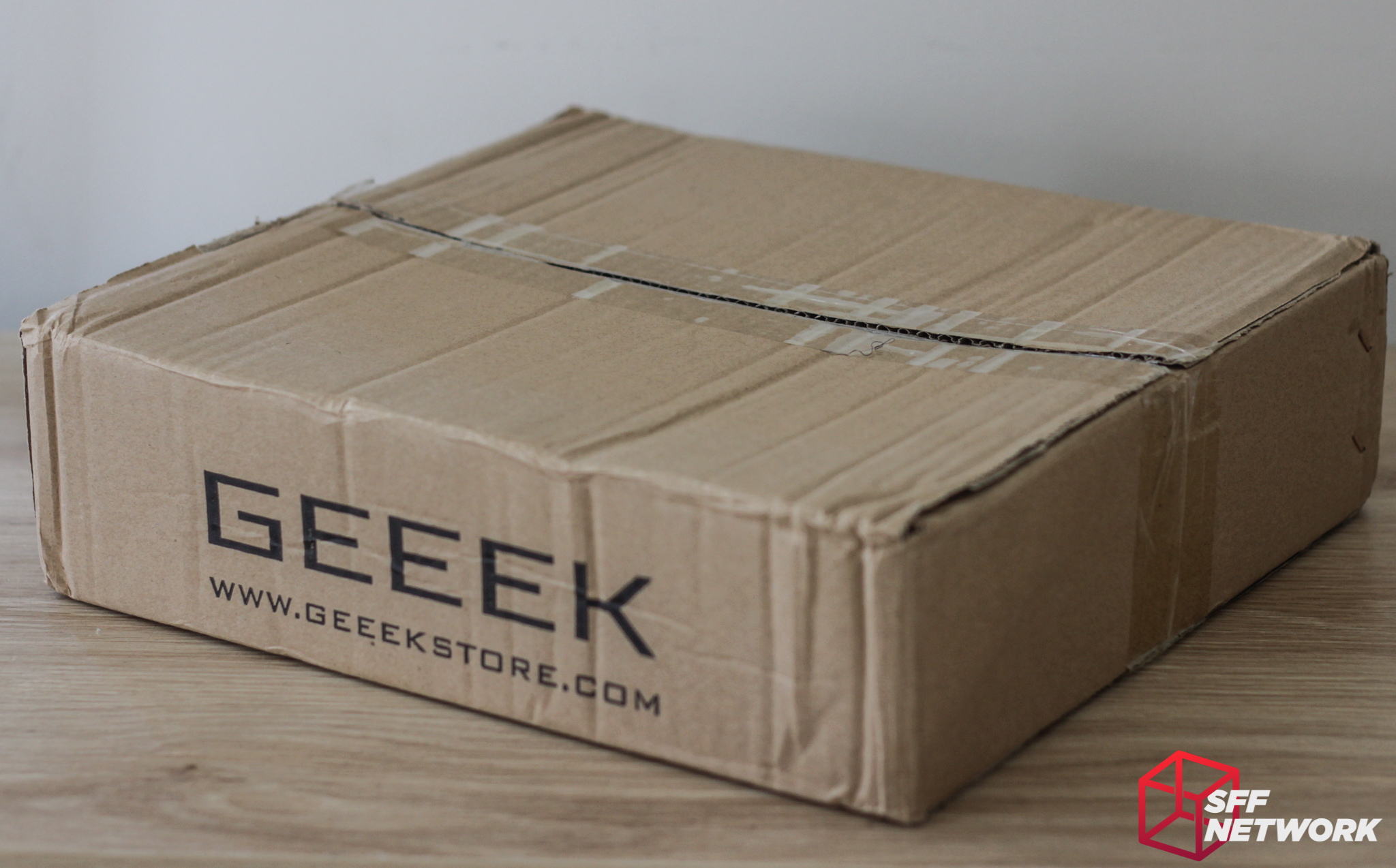
The A30 is delivered in a subtle brown box, with no flashy graphics or colour printing – a cost saving measure that helps bring the cost of this product down.
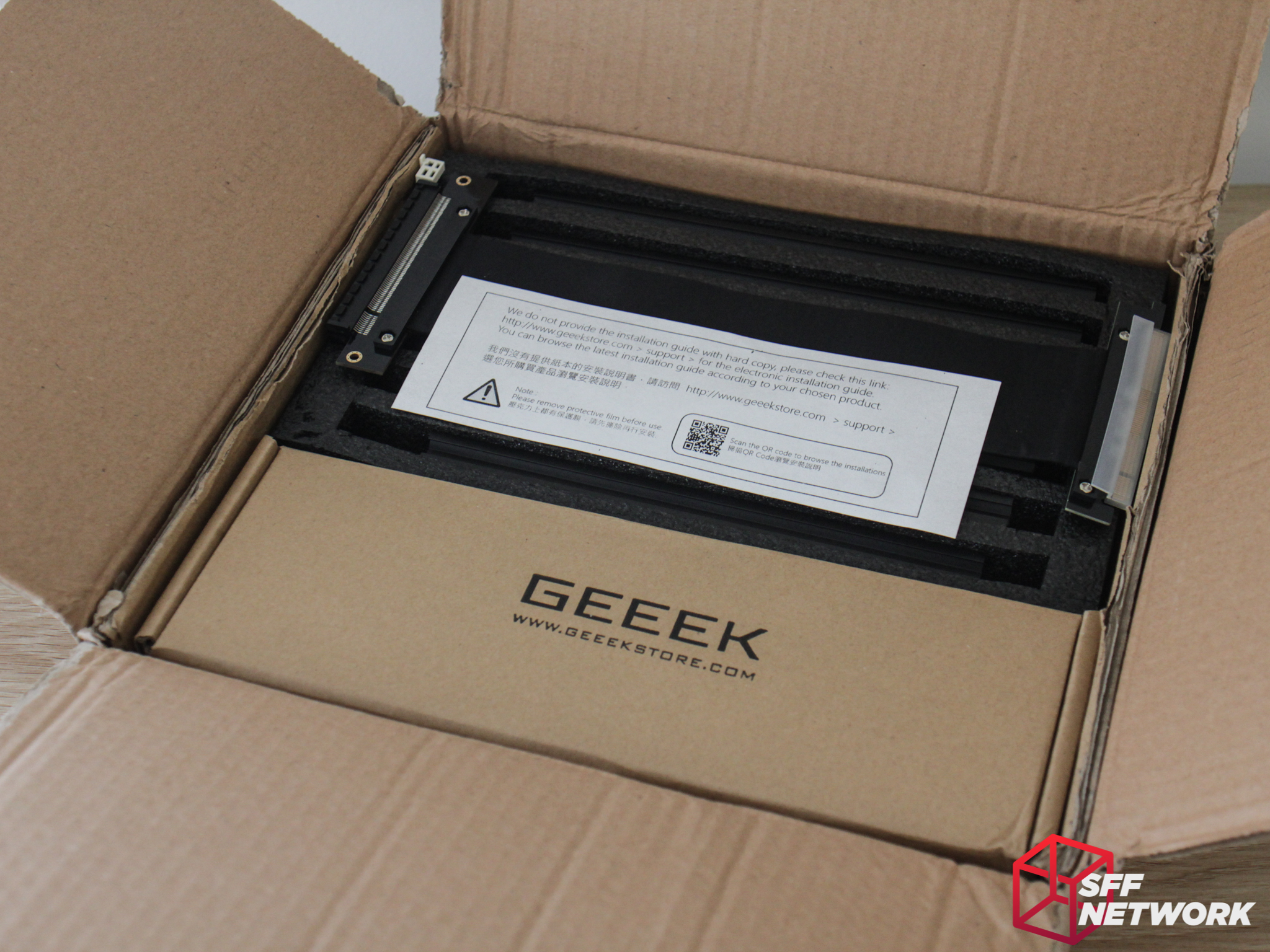
Opening the box, we can see that the chassis is well packed – with the metal parts in die cut foam, the accessories in a separate box, and the (optional) Li-Heat riser placed on top. The note on top guides you to Geeek’s website to find the chassis manual – no printed instructions come with the A30.
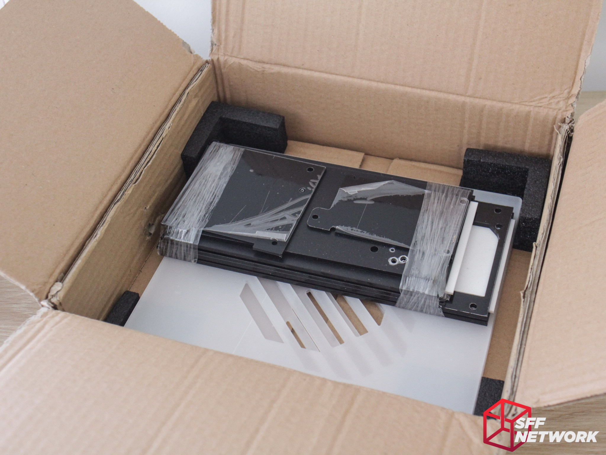
Taking off the accessories box and foam tray reveals the panel portions of the case – protected with foam corners. I feel that a layer of soft foam in here would help stop the parts from sliding around during shipping – however the acrylic is protected by plastic film on both sides.
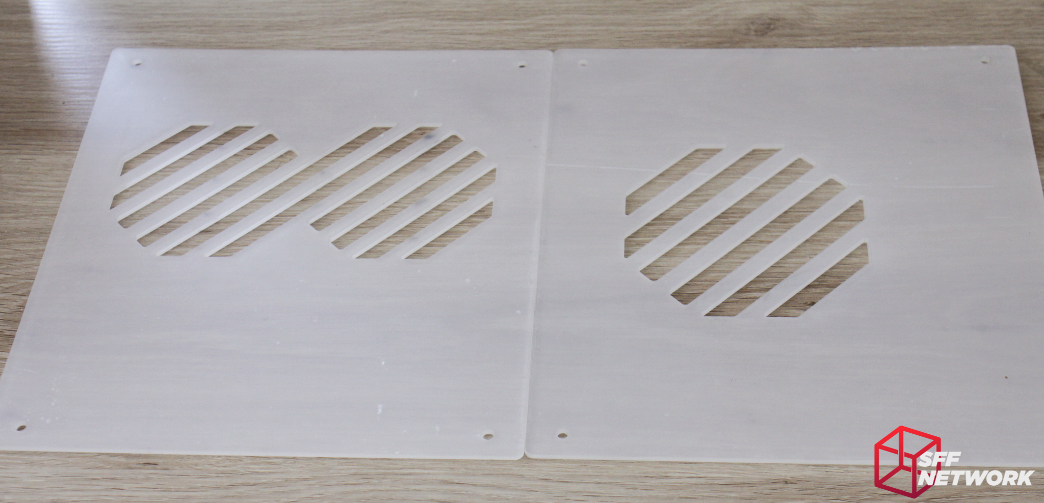
The two side panels, in an opaque white aesthetic. Just kidding – these are clear panels, the cloudy white is the aformentioned protective film.
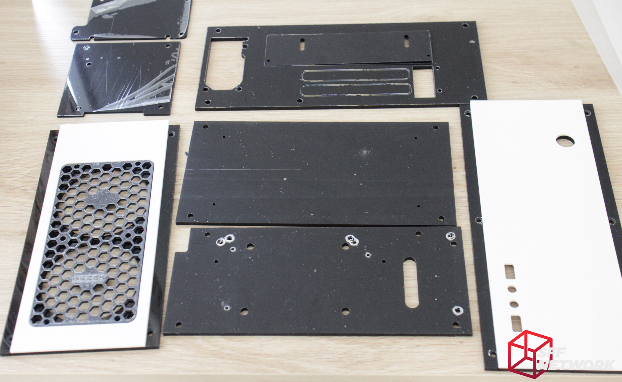
And the rest of the panels. It’s interesting to note that the top and front panels are pre-assembled, bonded together with smoked grey and white acrylic for aesthetic reasons. All the acrylic used in the A30 is 3mm thick – pretty standard fare.

Extruded aluminium sections – 6 are identical, whereas the third from the left is shorter – we will see why during the build. The extrusions are of a relatively thin cross section, however, they do seem sturdy enough for the construction of the A30.
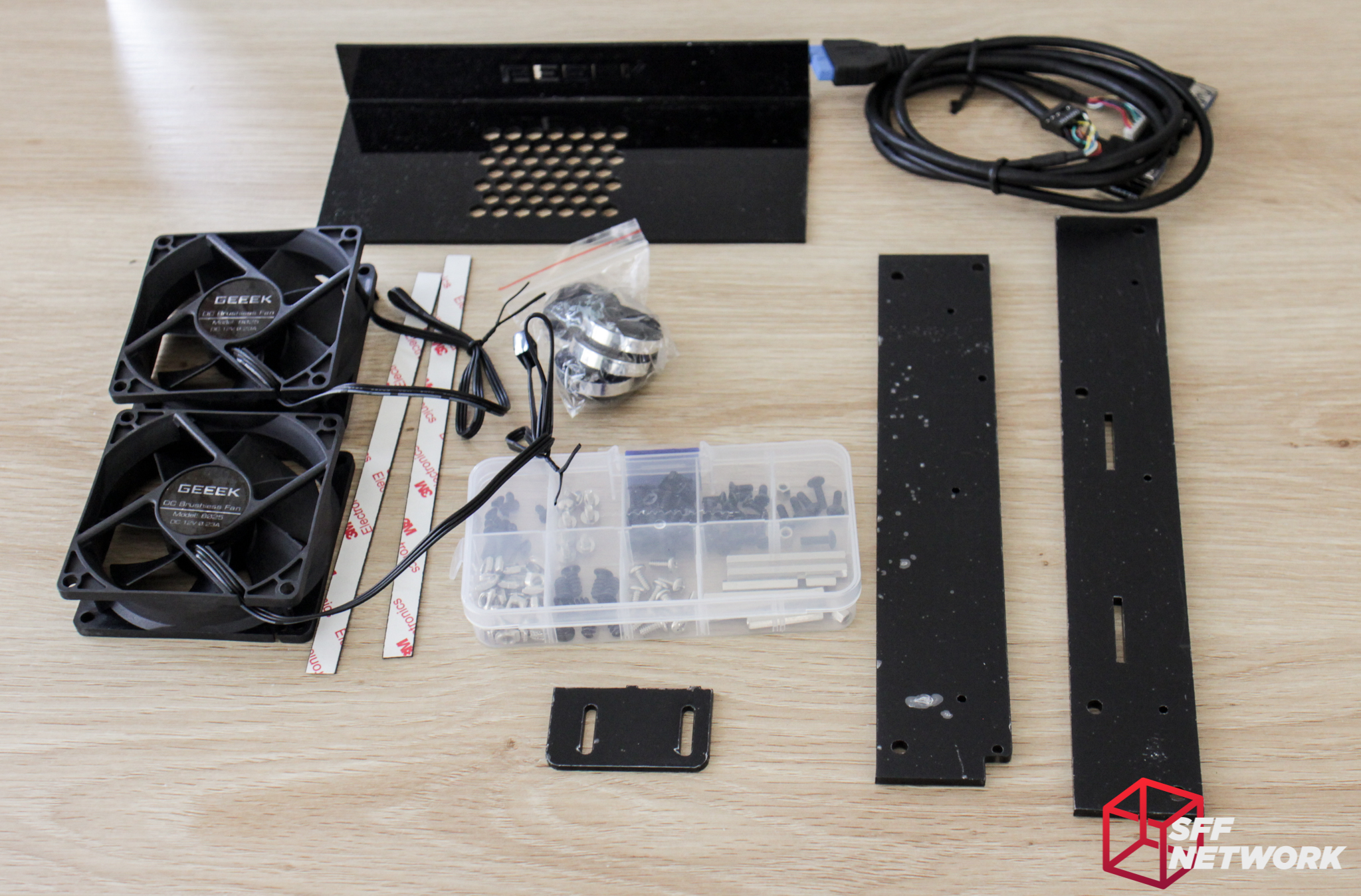
Opening up the internal cardboard box reveals a plethora of parts – both included with the base chassis, and optional. Standard componentry are the case feet, the front IO section, the three acrylic panels and the box of screws.
The optional parts in this shot are the two Geeek branded 80 x 25mm fans, the 3M branded magnet strips, and the PSU cover at the top of the photo. Adding the the PSU cover and strips to your cart alongside your A30 adds US$6.99, the pair of fans are US$5 and the Li-Heat riser is US$29.99.
The Build
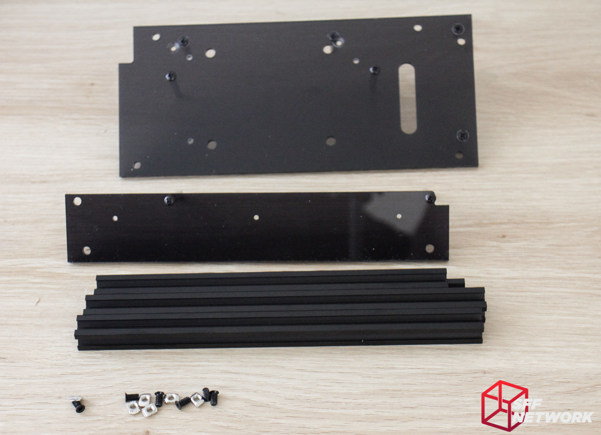
As we go along, feel free to follow the manual, found here. First step is finding the parts we need – namely two M3 x 10mm screws, two 40mm standoffs and an acrylic section. This particular piece forms part of the motherboard mounting.
Done!
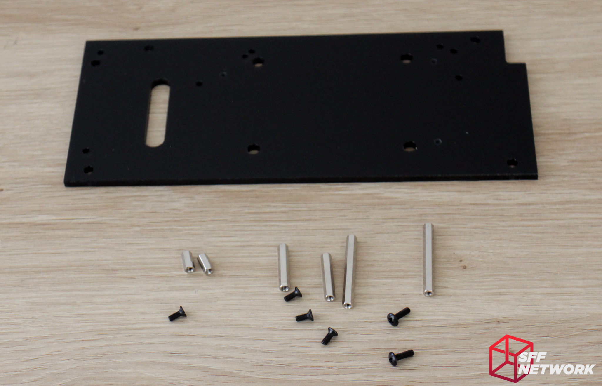
This panel forms the other part of the motherboard tray, as well as mounting for the PCIe riser and a 2.5 mm drive. Screws used here are two M3 x 10mm screws, four M3 x 8mm screws, and two each of 40mm, 25mm and 10mm standoffs.
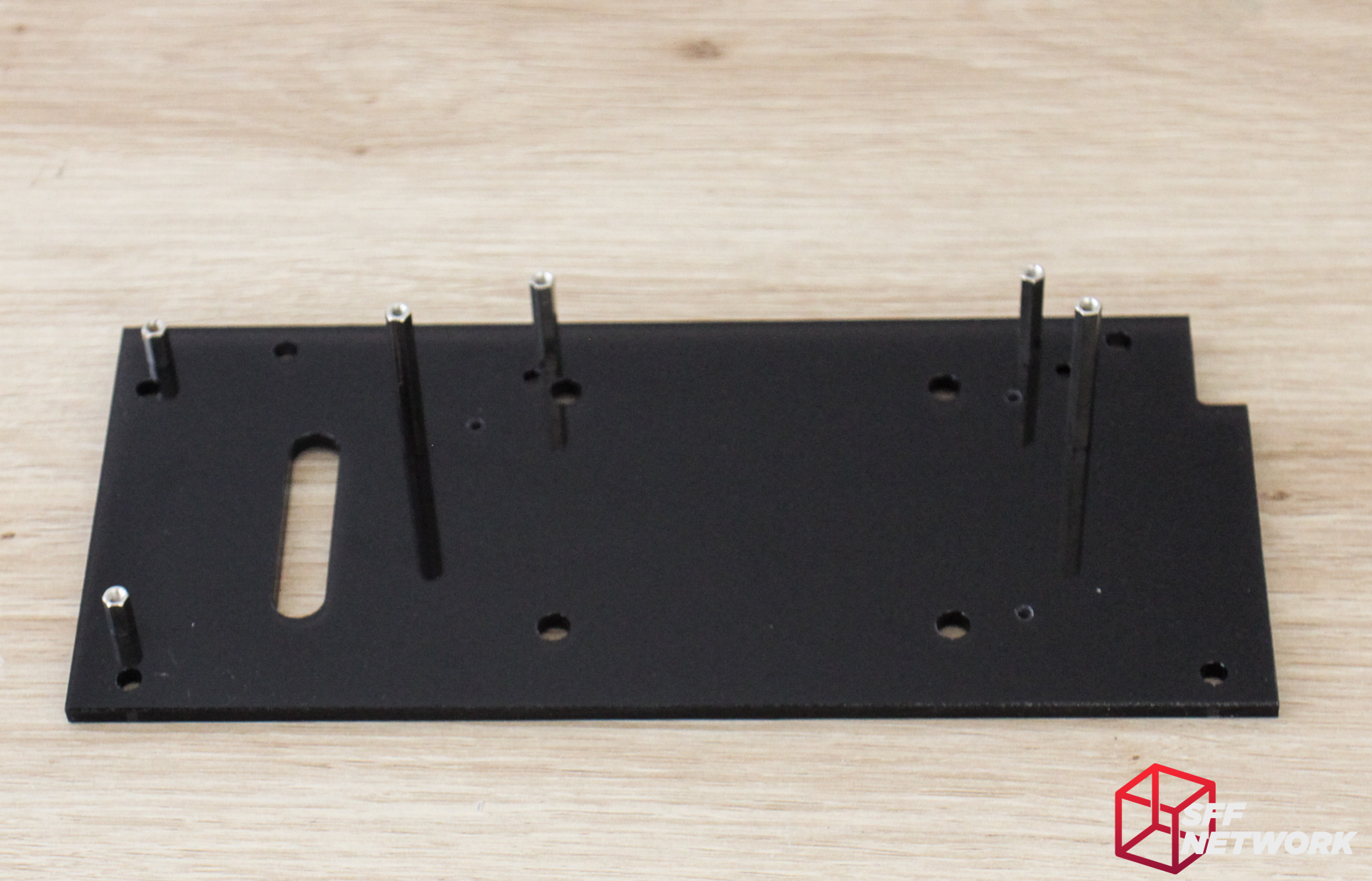
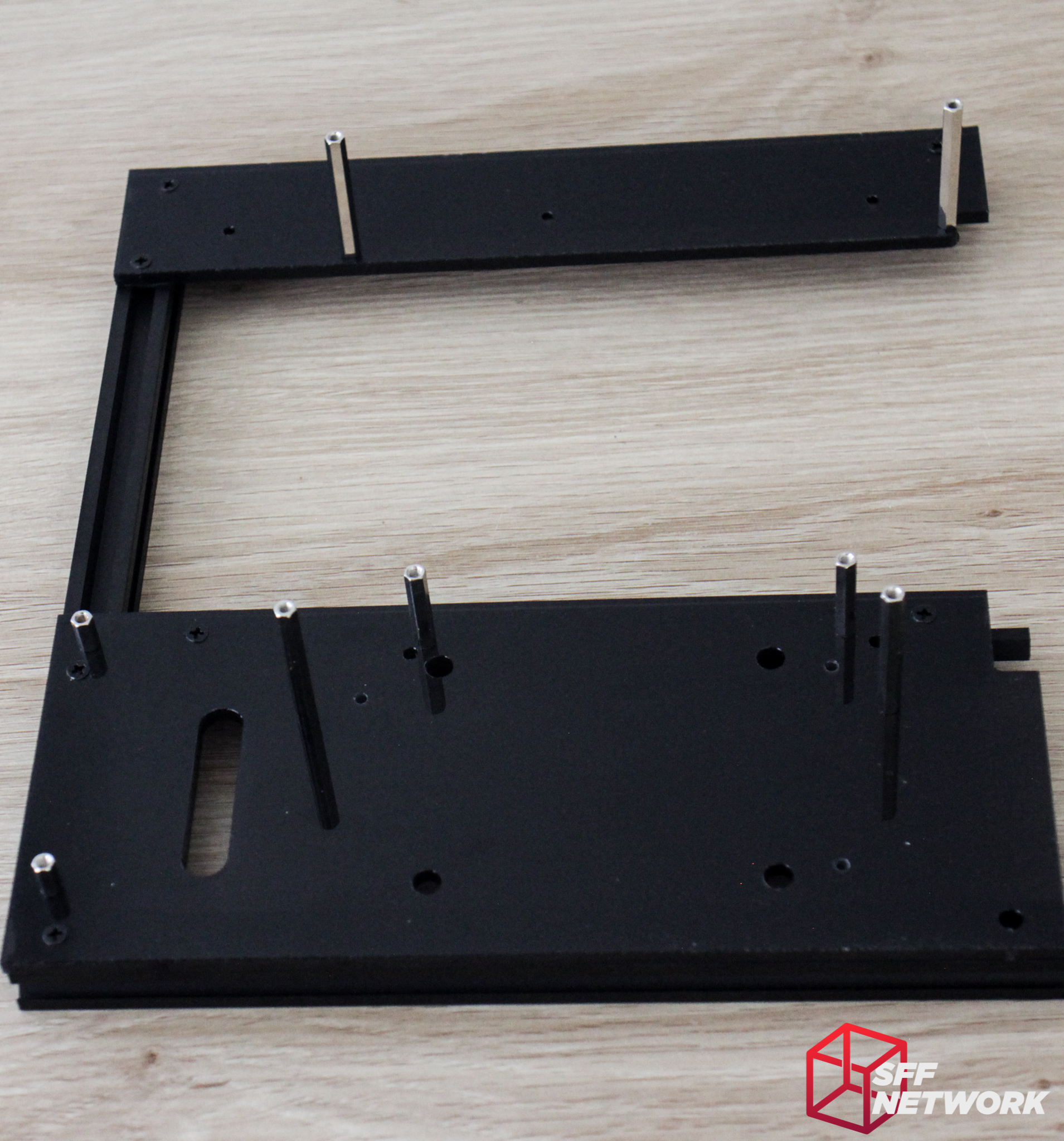
And mounted. It’s important to note here that the instructions aren’t very clear, which is a shame. the 25mm standoffs (top of the image) here are for the flexible PCIe riser mounting. What isn’t mentioned in the manual is which ones to use for the optional Li-Heat riser. In this image, I’ve used the wrong holes, which I didn’t discover until three-quarters of the way through the build. I wasn’t happy! There are two holes at each location for these standoffs – the “lower” ones in this image are for the Li-Heat riser.
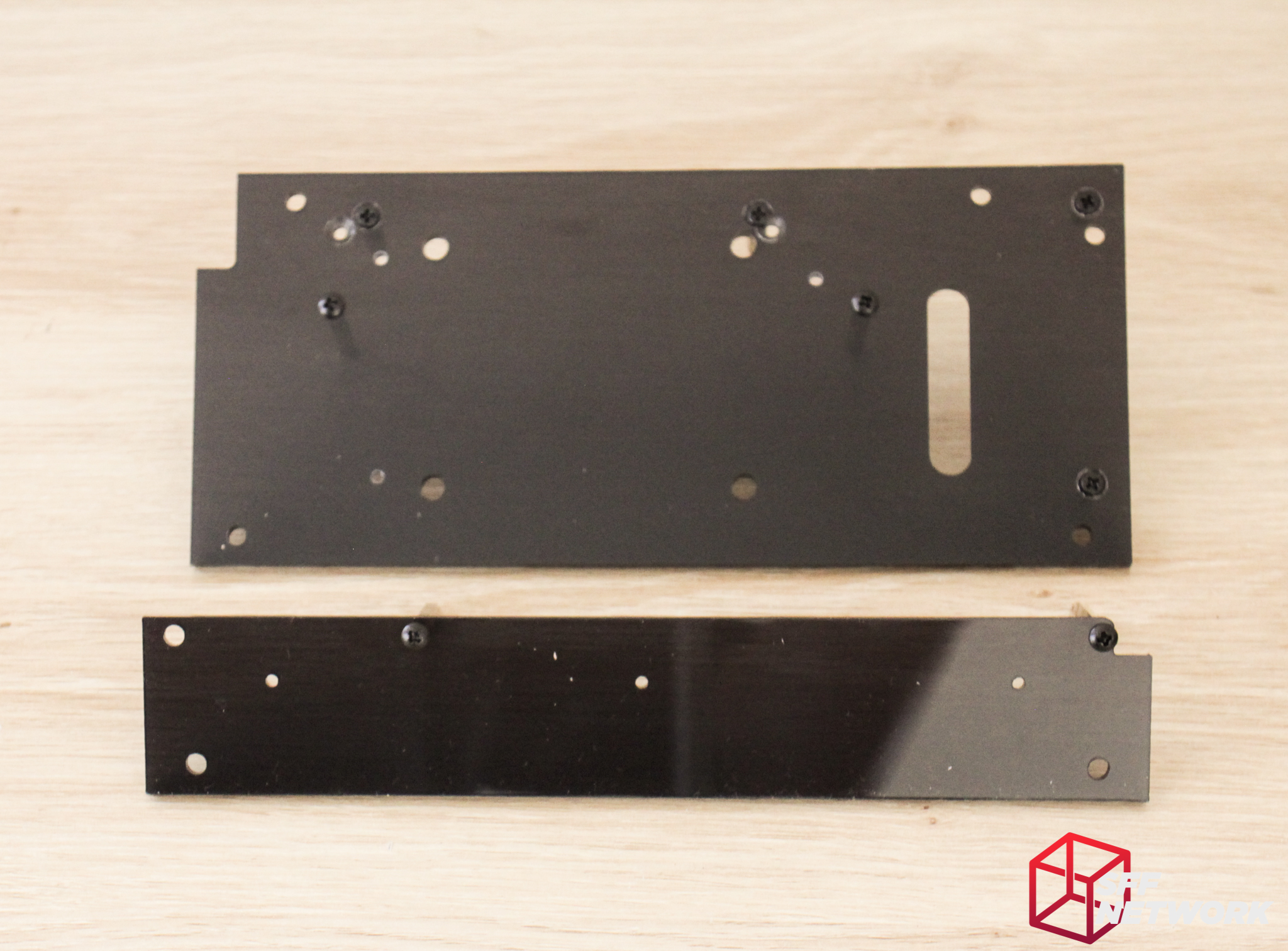
The two panels completed and ready for the next step..

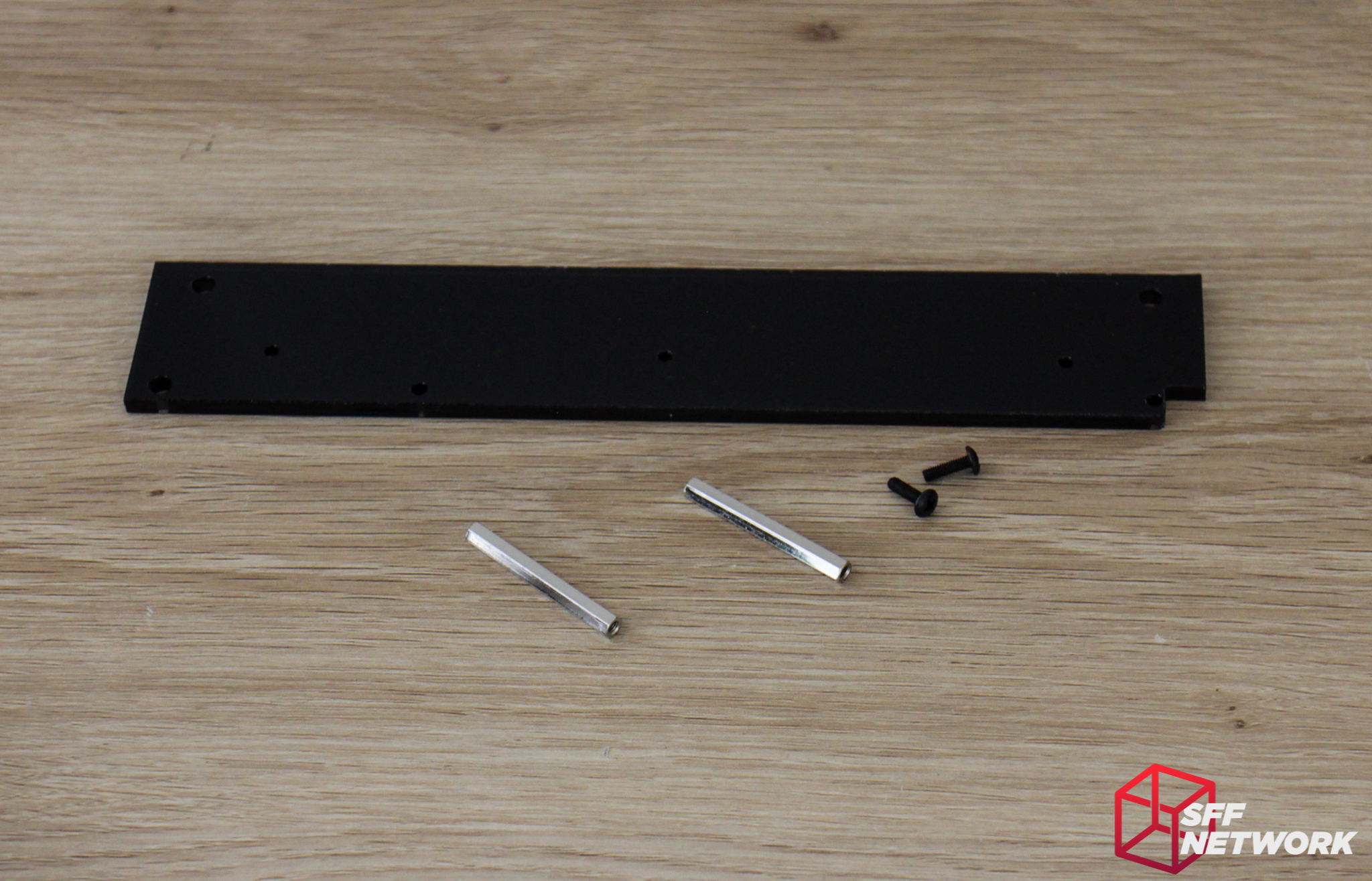
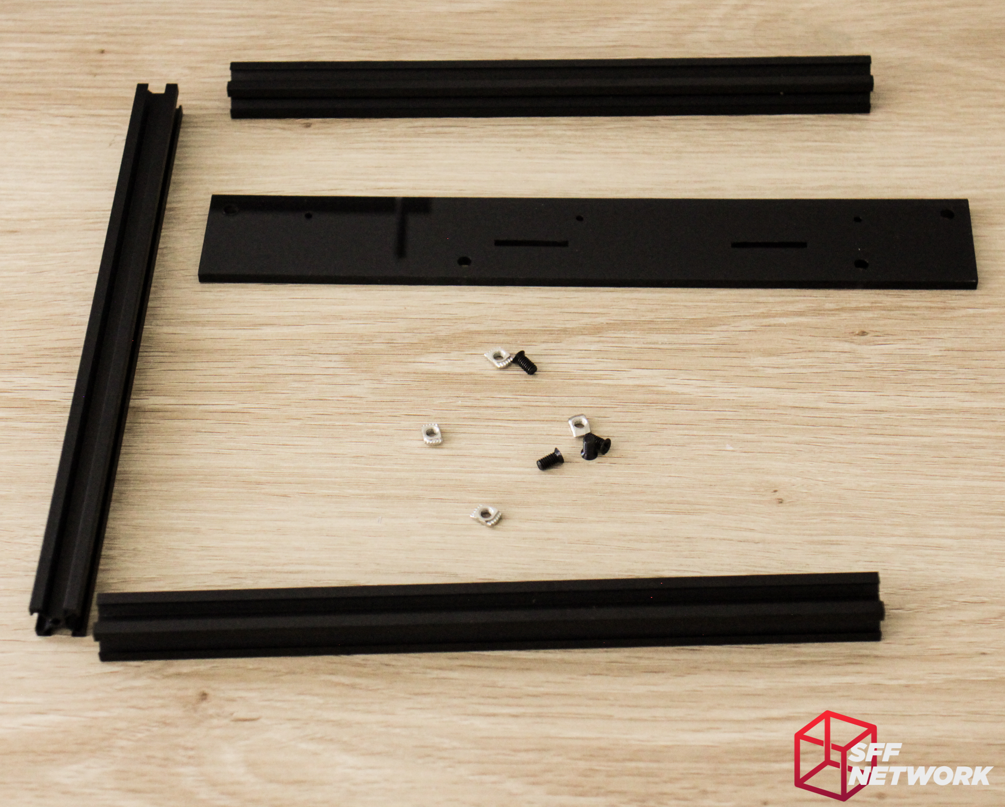
This is the shorter of the aluminium extrusions, and a single spacer. These together match the length of the longer extrusions, and ends up providing room for the GPU IO bracket.
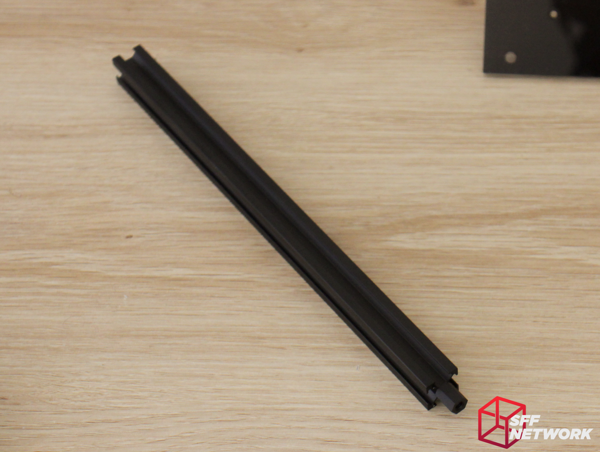
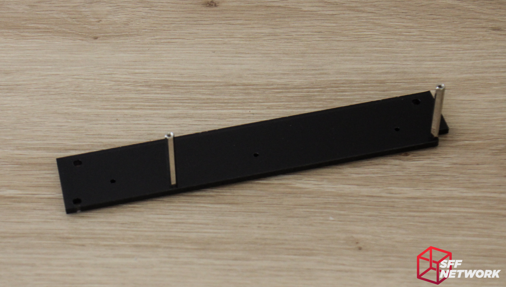
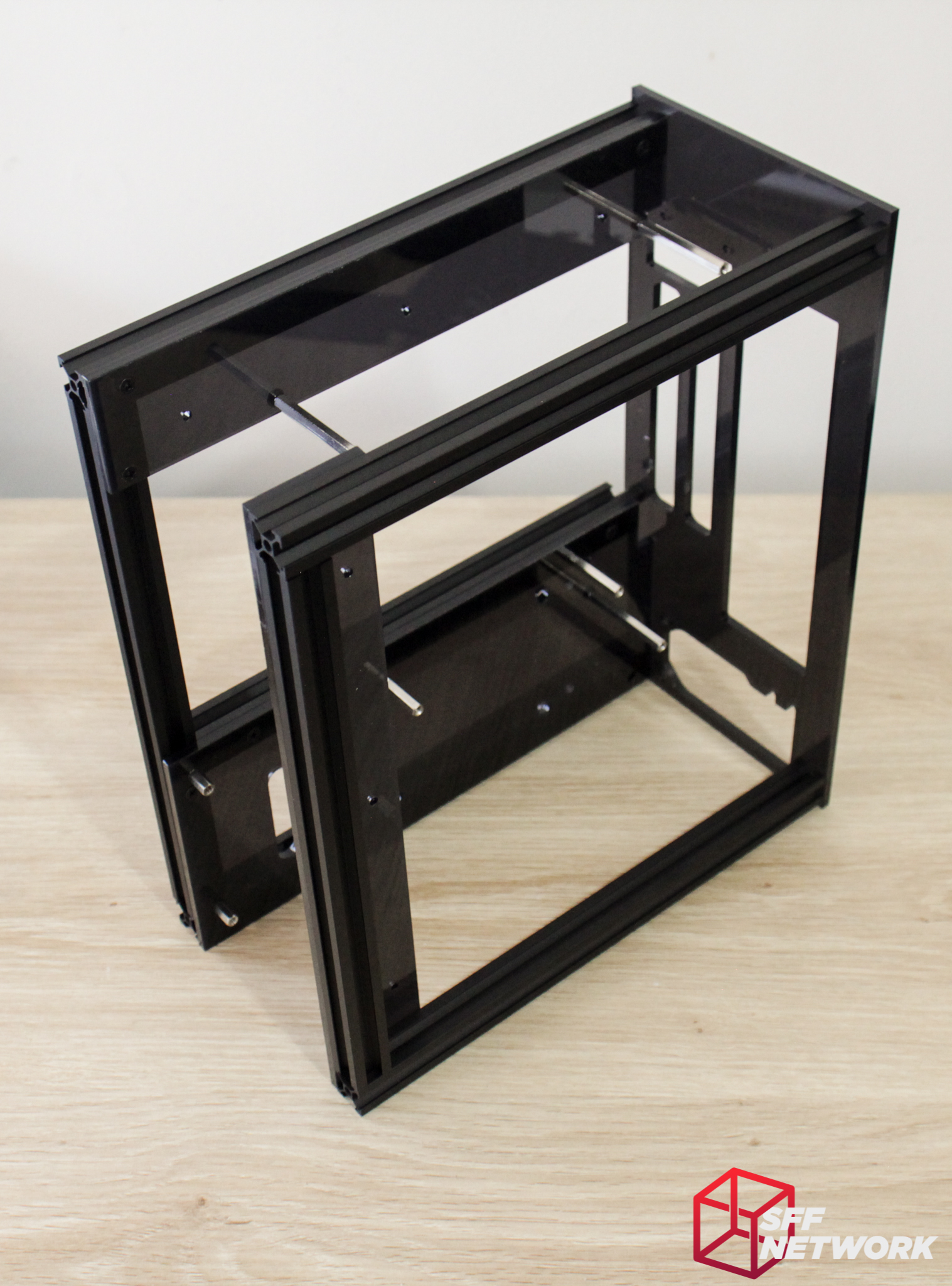
Together at last!
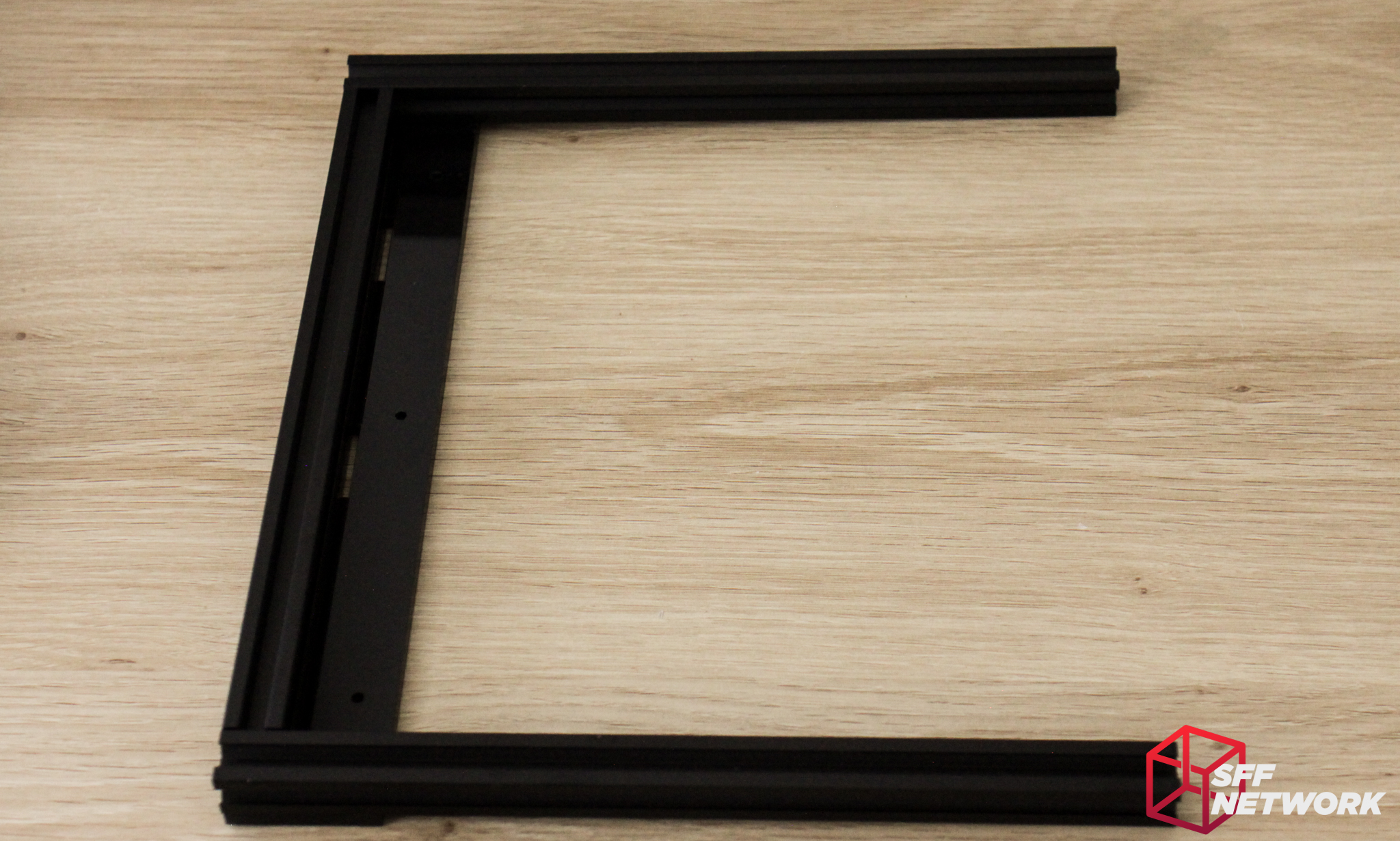
Right, now on to the next step. Added to the above parts we’ve put together, six M4 x 8mm screws and six nuts are collected. The screw and nut combos mount the acrylic panels to the extrusions, holding the whole unit together!
Even at this stage, I’m amazed at how sturdy this is for something made from thin aluminium and acrylic.
On to the next section. The acrylic section here forms part of the front bracketry. This is all screwed together with the M4 x 8mm screws and nuts shown here.
The acrylic in the case is used for structure as well as aesthetics – the aluminium extrusions are not connected directly in any way!

Let’s throw this all together with the addition of the rear panel and five M3 x 8mm screws.

I noticed a bit of warping in the frame at this point – a side product of the aluminium sections not being directly connected. A few moments loosening strategic screws, levelling the chassis on a flat surface, and re-tightening the screws fixed this with no issues.
And from the front quarter view!
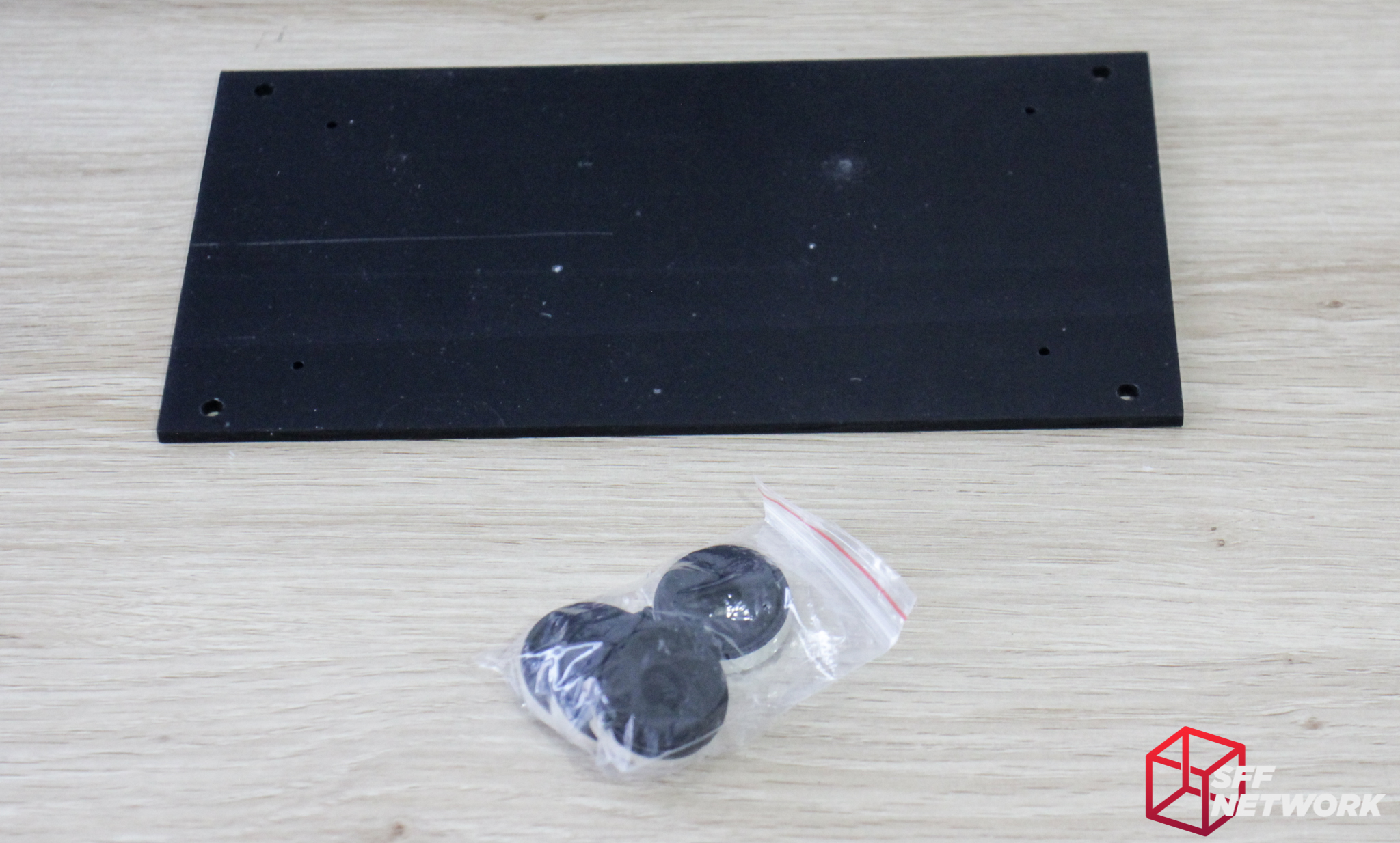
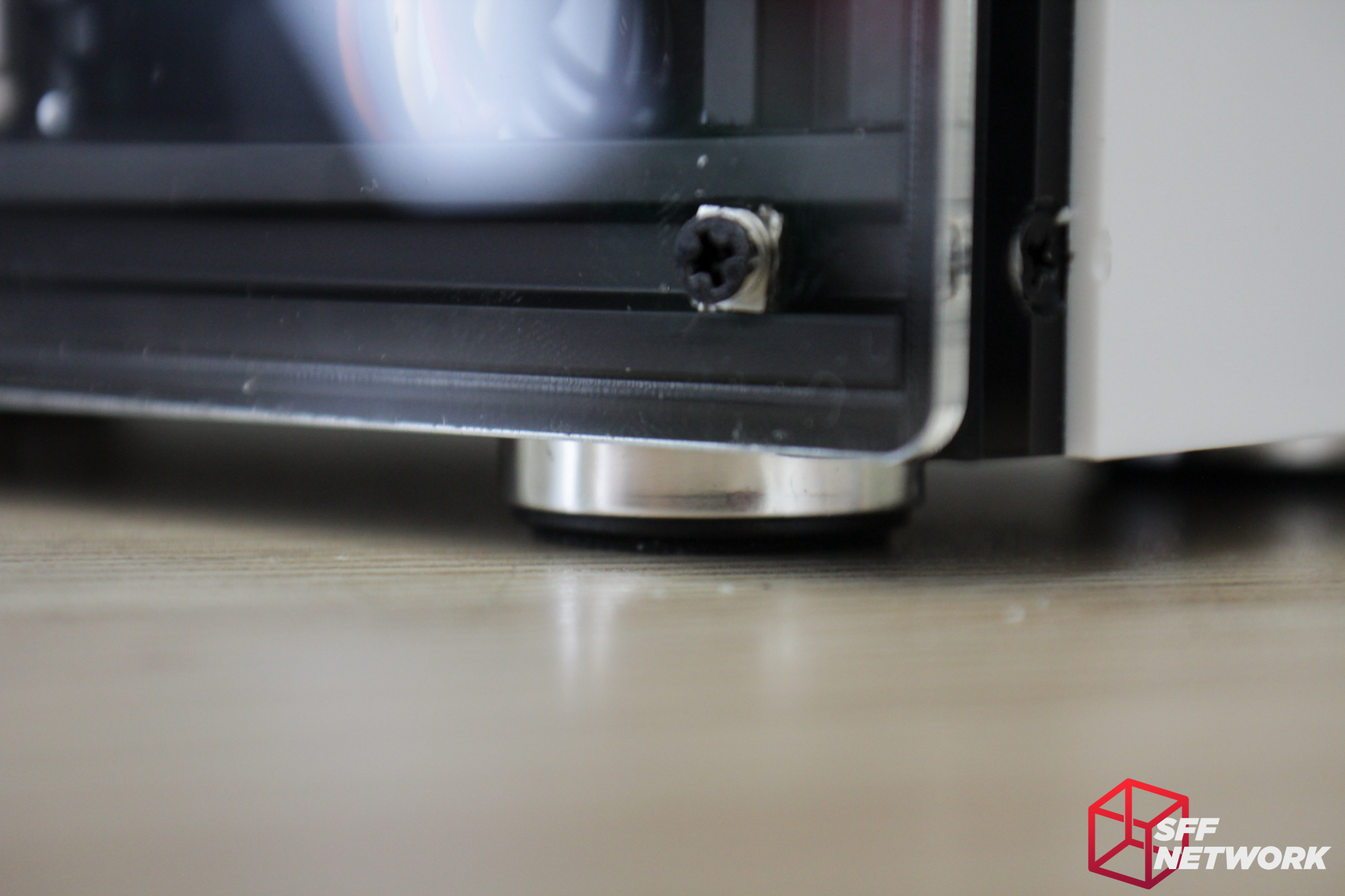
Now for the bottom. The included feet are of the cheap plastic variety, but they do the job.
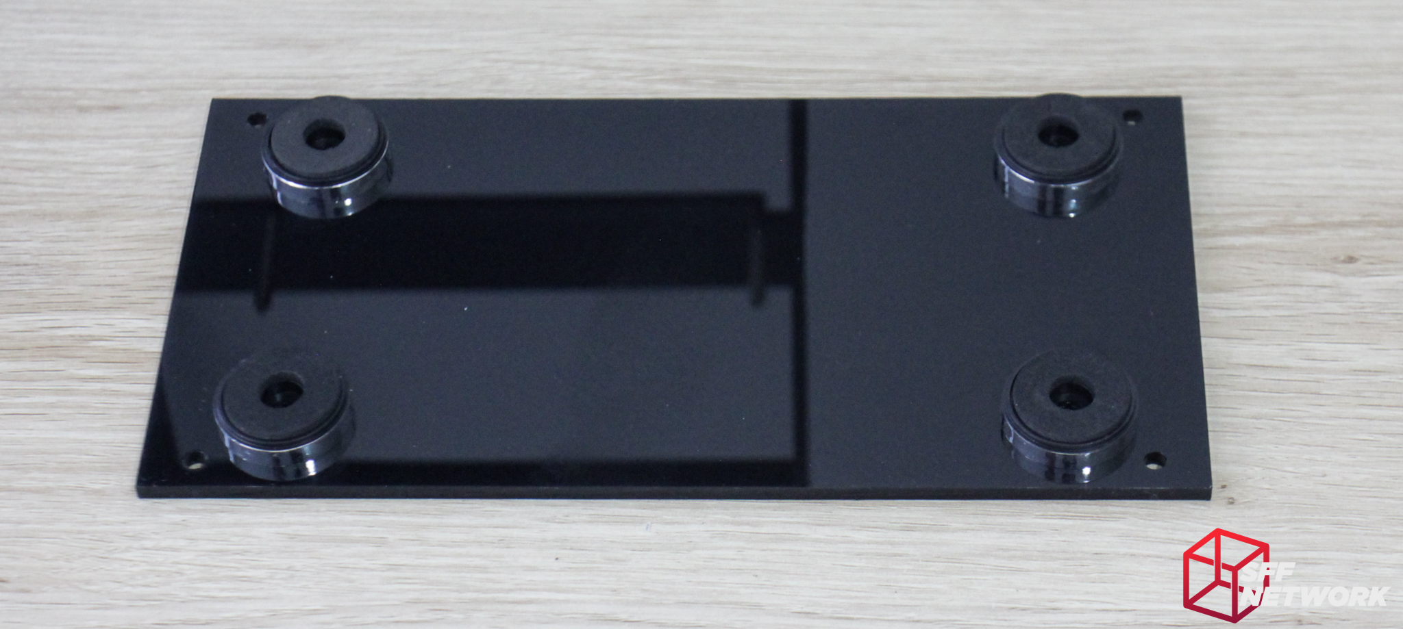
Pretty simple really.
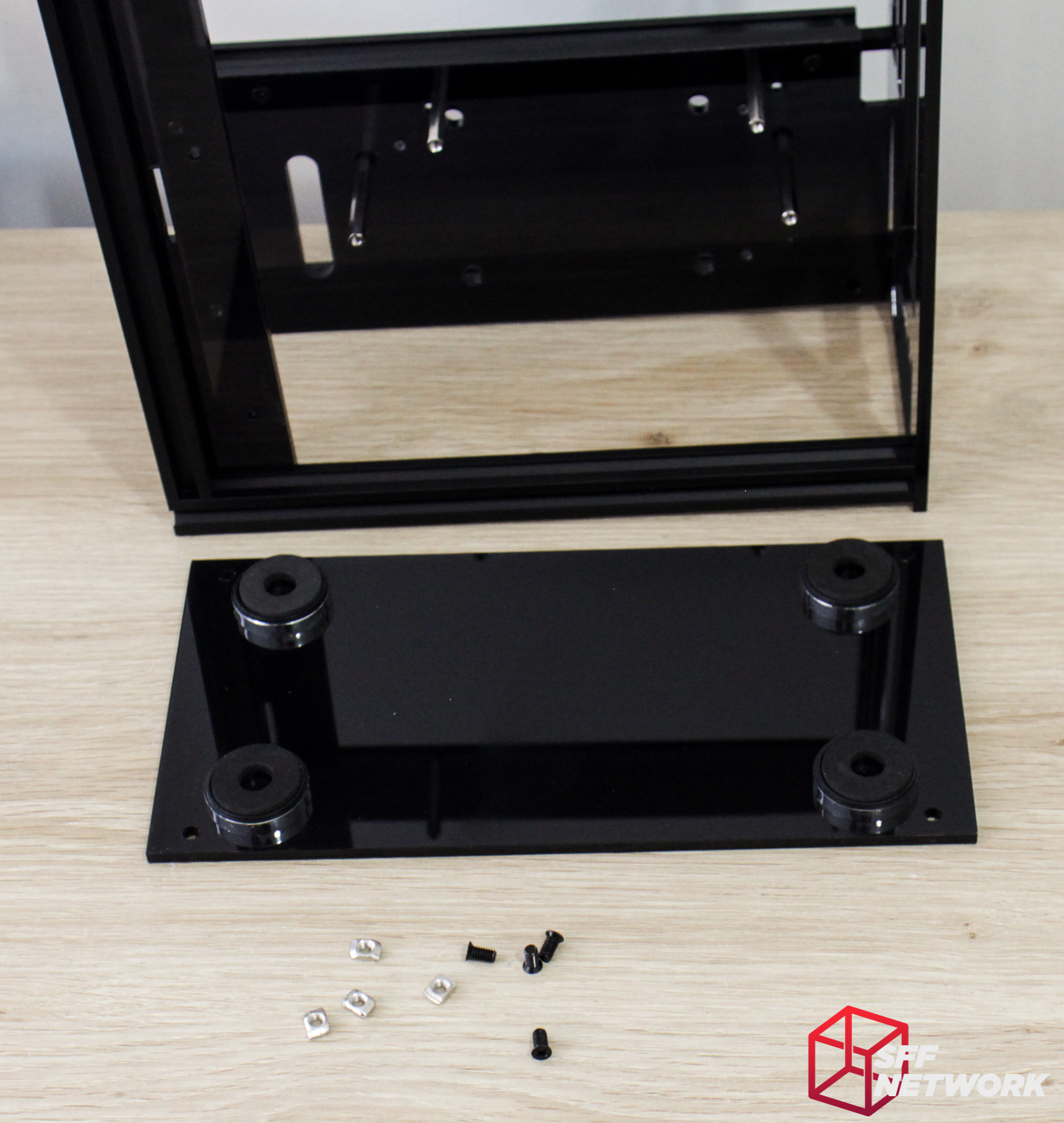
More of the M4 x 8mm screws and nuts and it’s time to get the A30 on it’s feet.

Done.

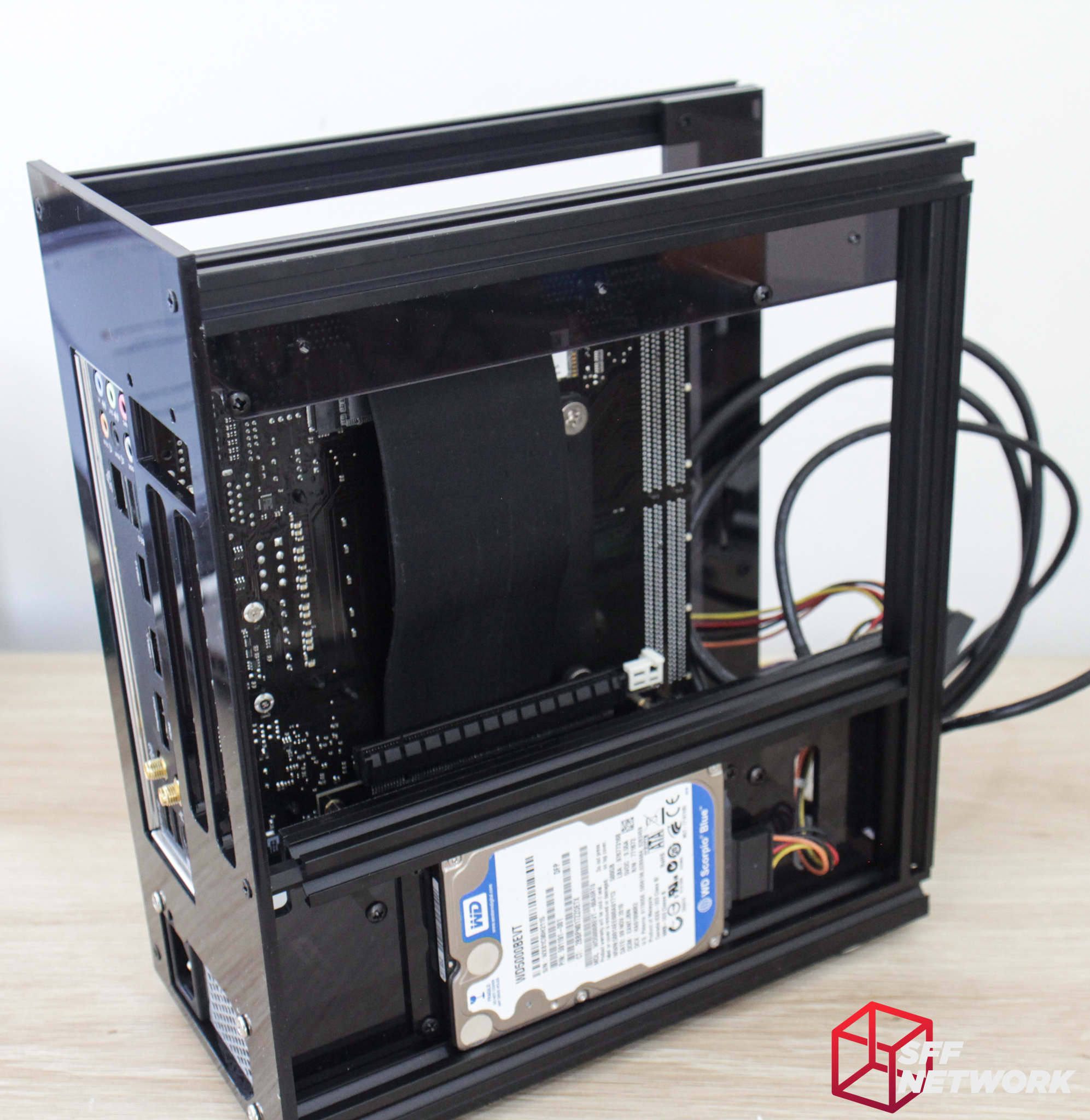
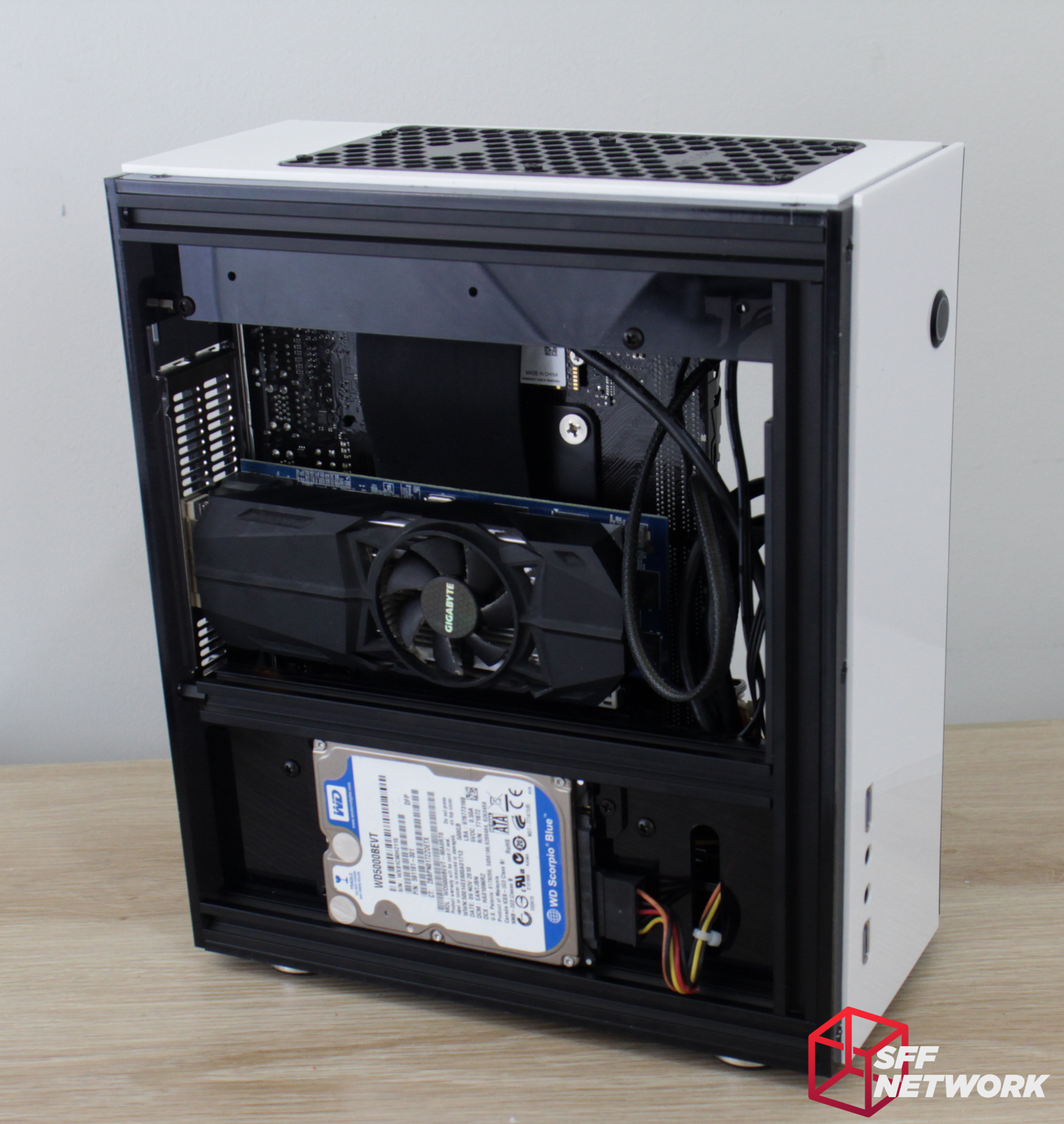
Let’s check our progress. The bottom and rear panels are in, motherboard standoffs are present, and some of the other mounting points are in. The layout of the case is now apparent – the GPu sits behind the motherboard, with both the motherboard and GPU facing their respective side panels.
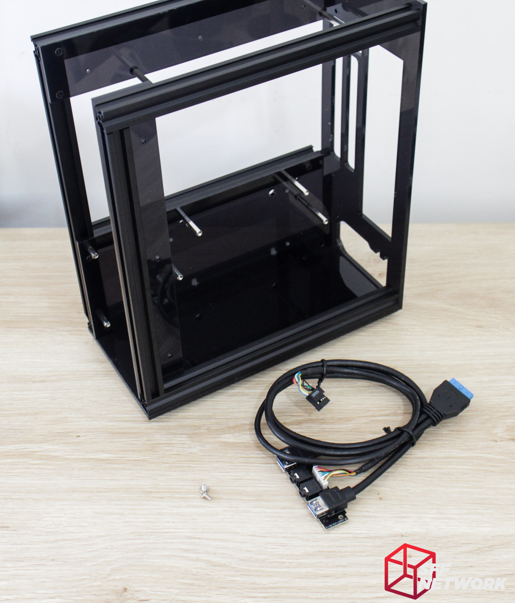
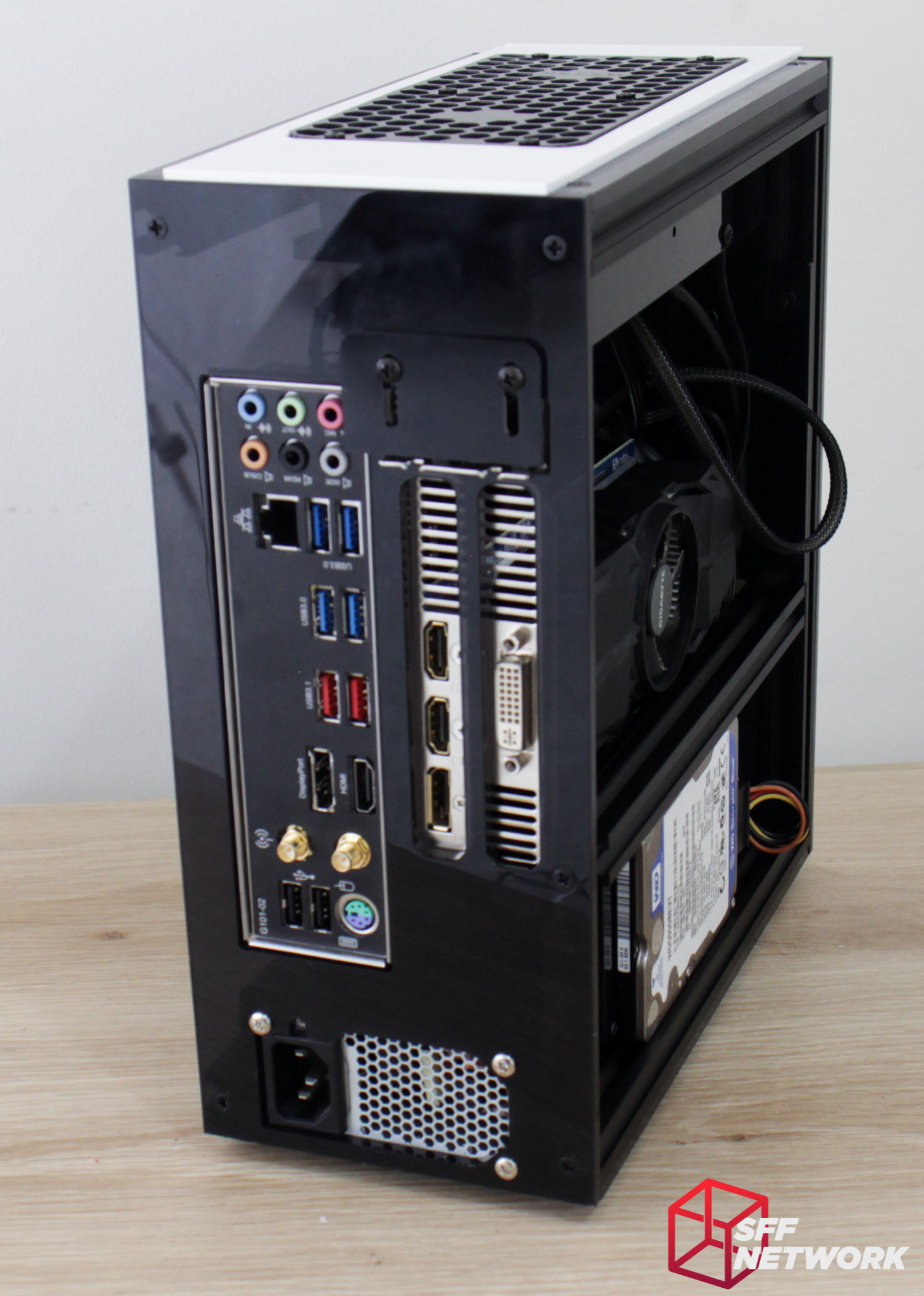
The front IO board includes two USB3 ports, headphone and mic jacks. Pretty standard fare these days.
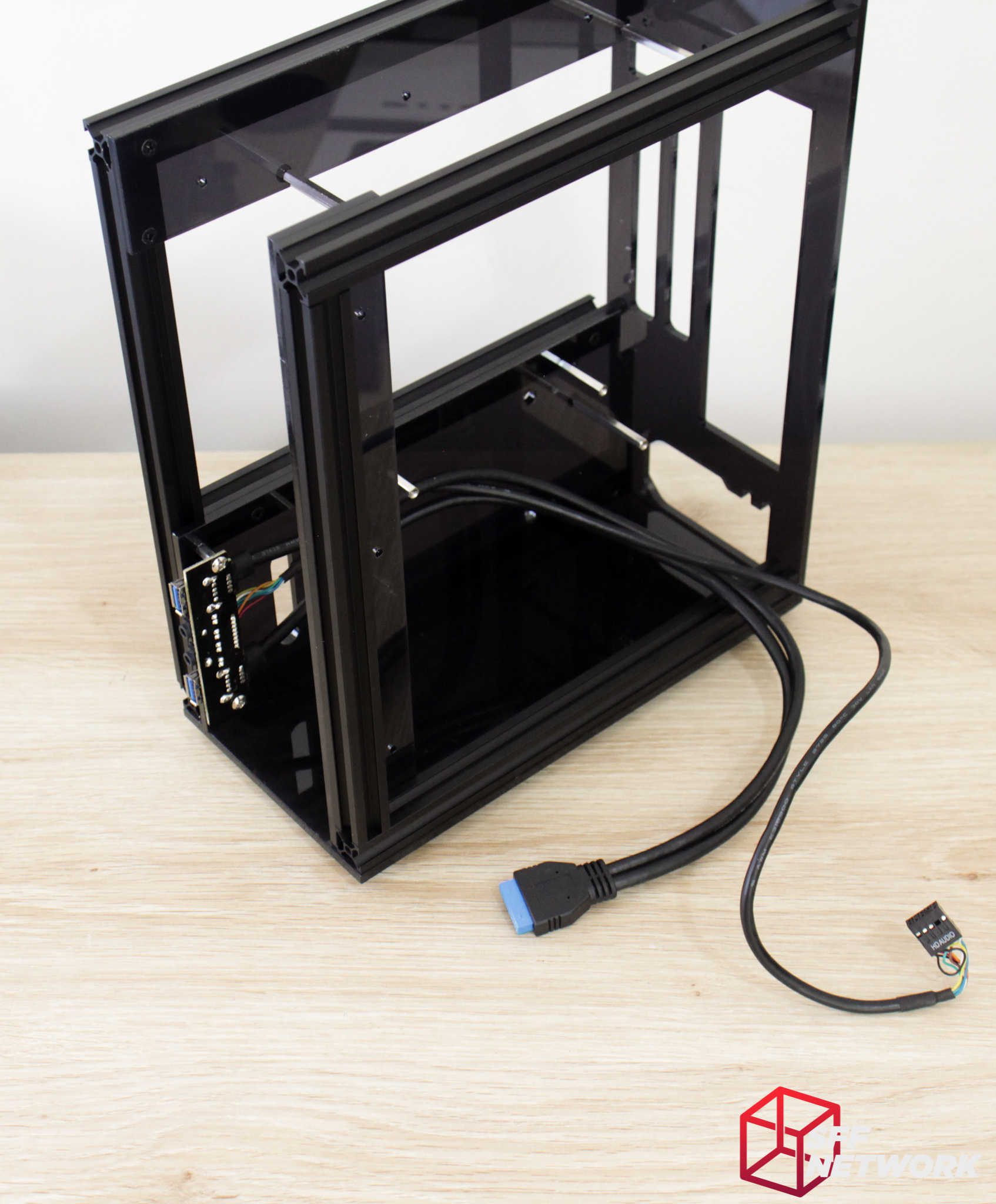
A couple of stainless (rather than black) M3 screws affixes this into place. There is sufficient length for any motherboard layout, as well as for cable management.
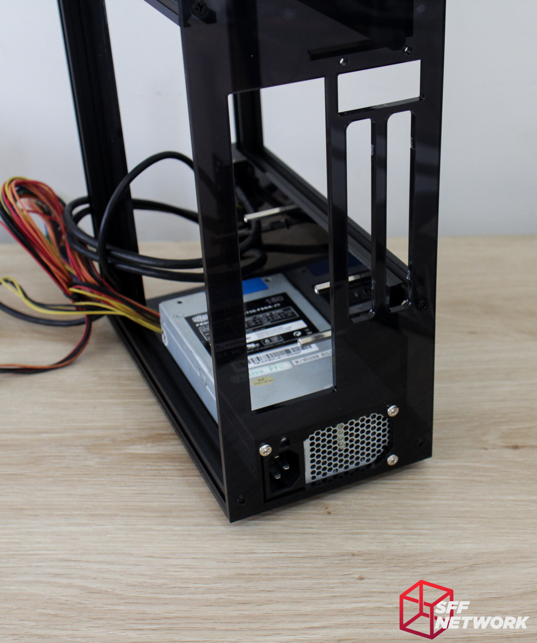
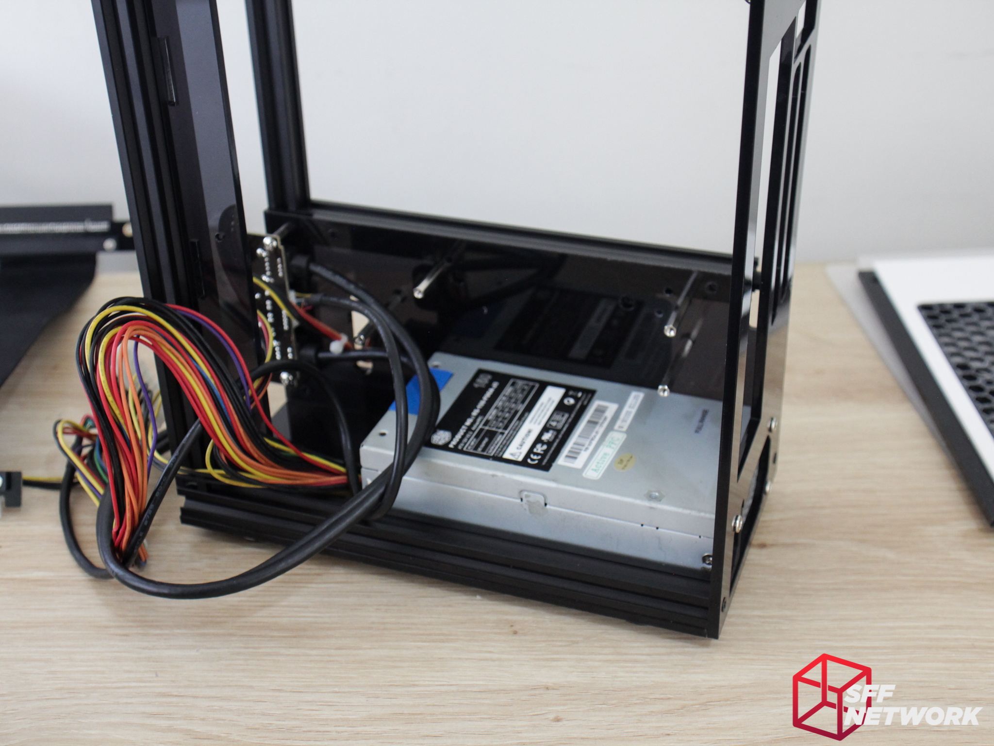
Mounting the Flex-ATX power supply is easy – but must be done at this step as the motherboard will make it difficult to remove after the fact. By the way, 1U power supplies will not fit – I tried!
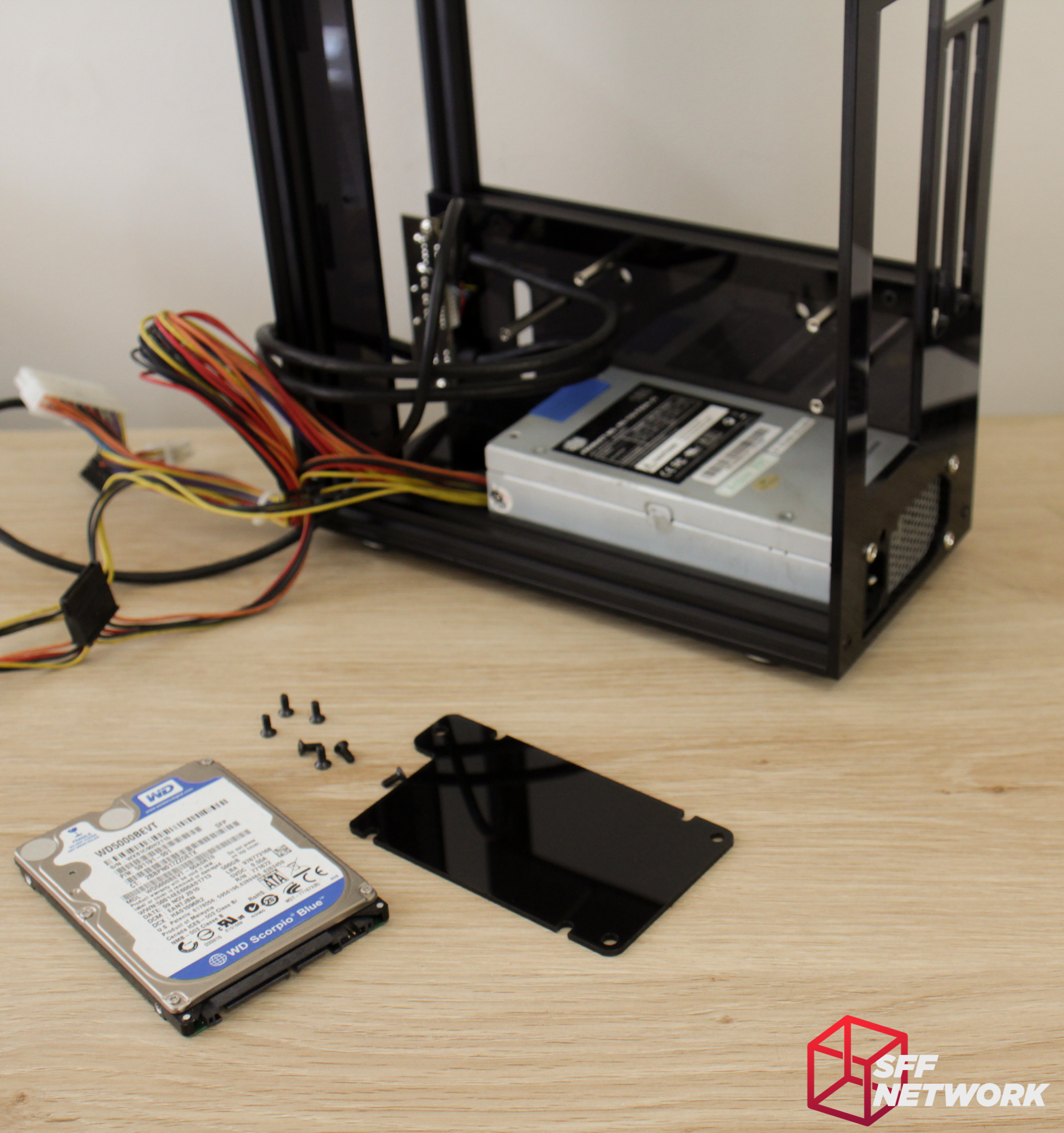
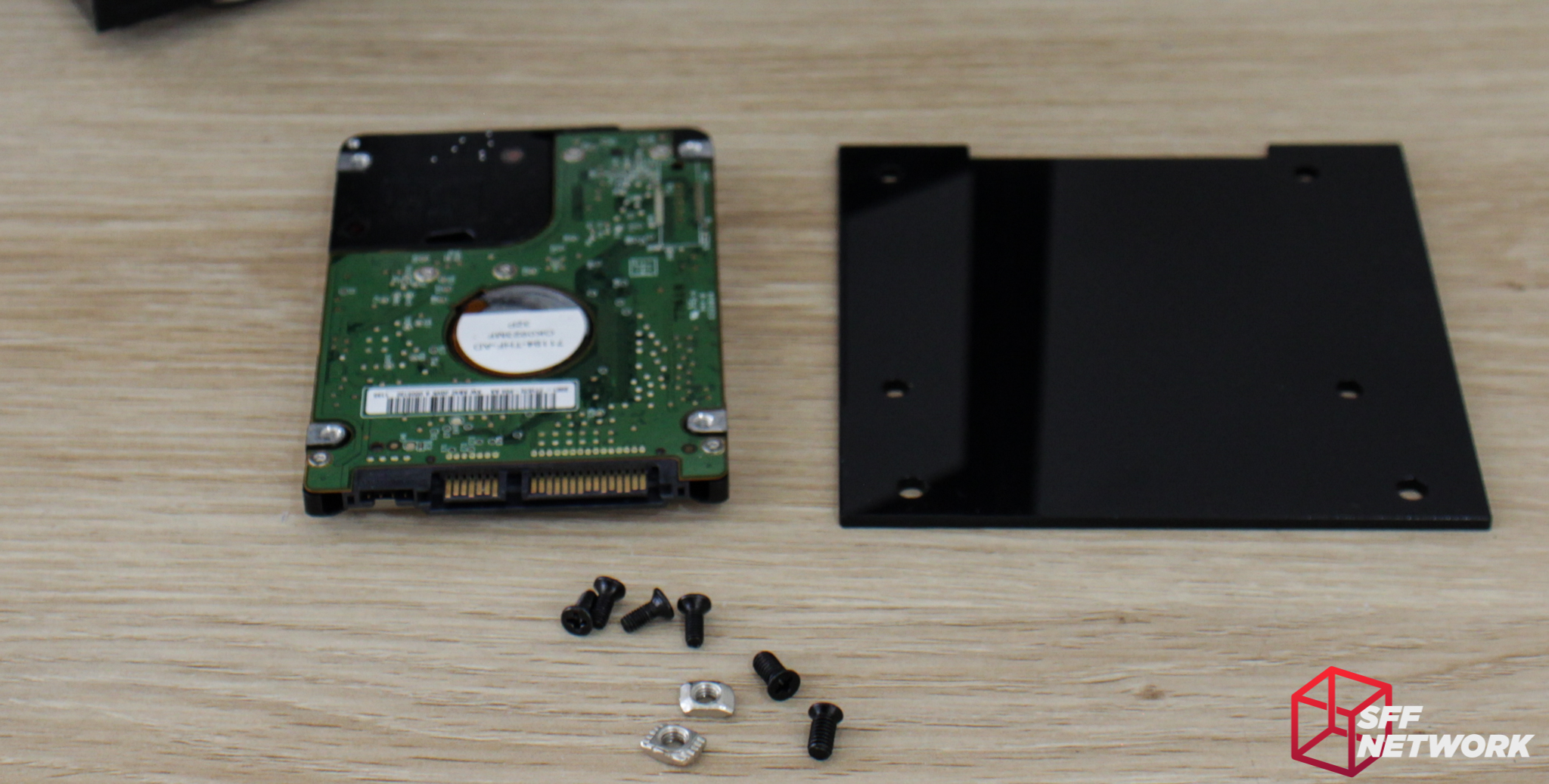
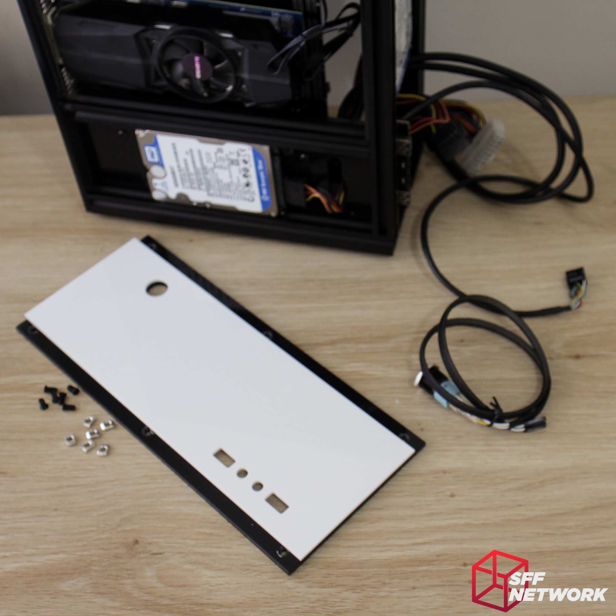
Now for an optional step. if you are wanting to mount a 2.5″ drive behind the motherboard, we use this panel, as well as a bunch of screws.
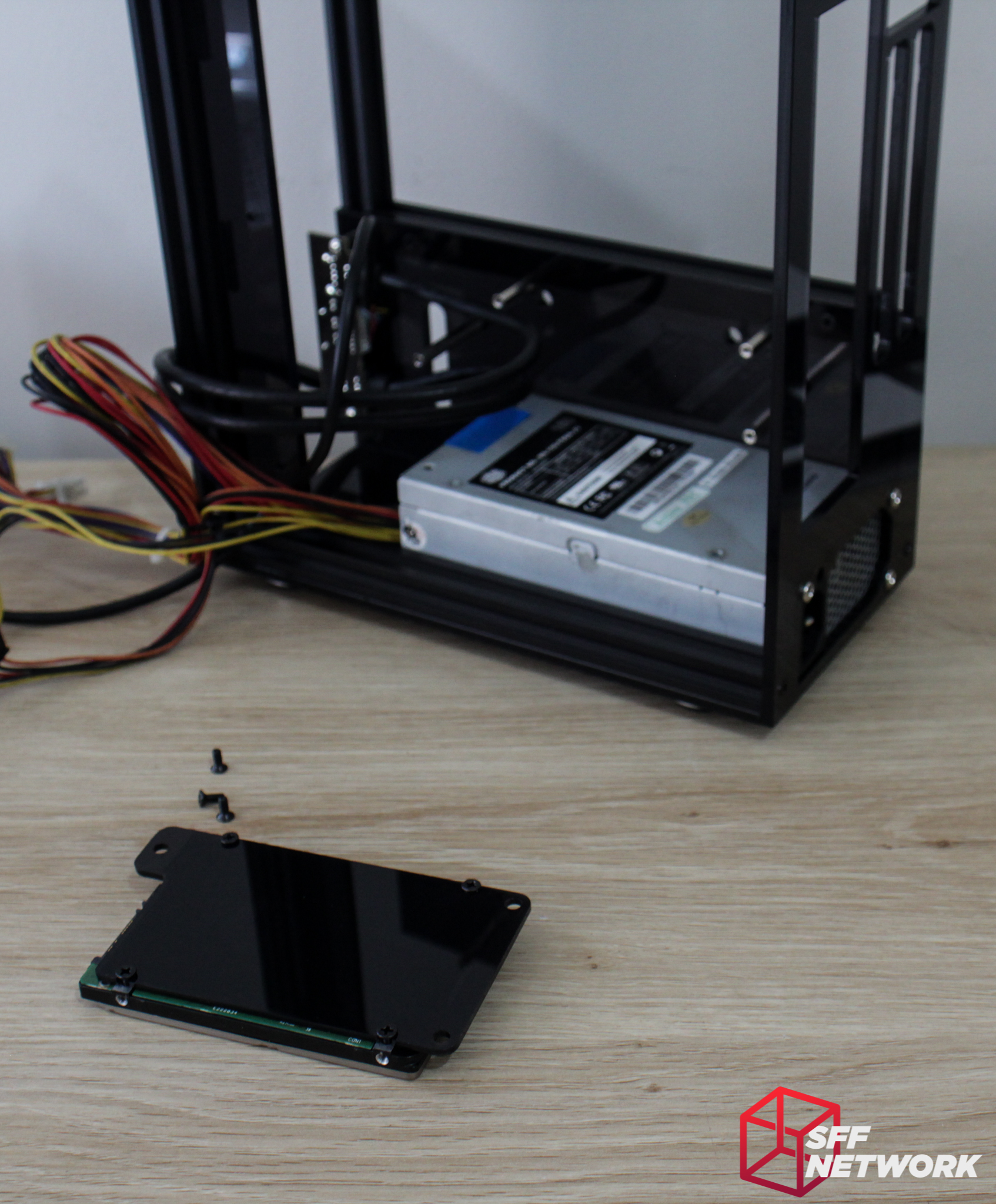
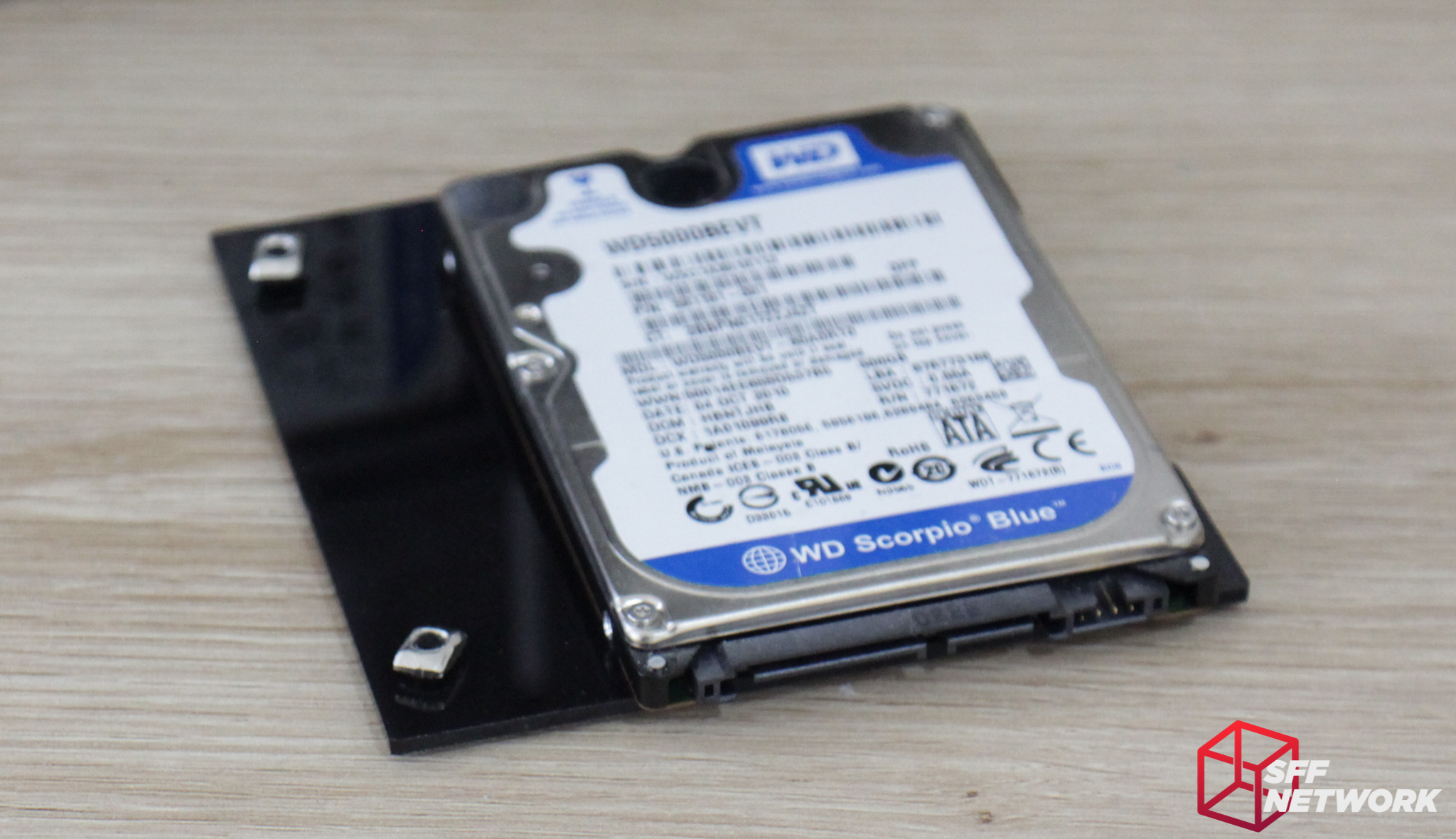
First, mount the drive to the panel..
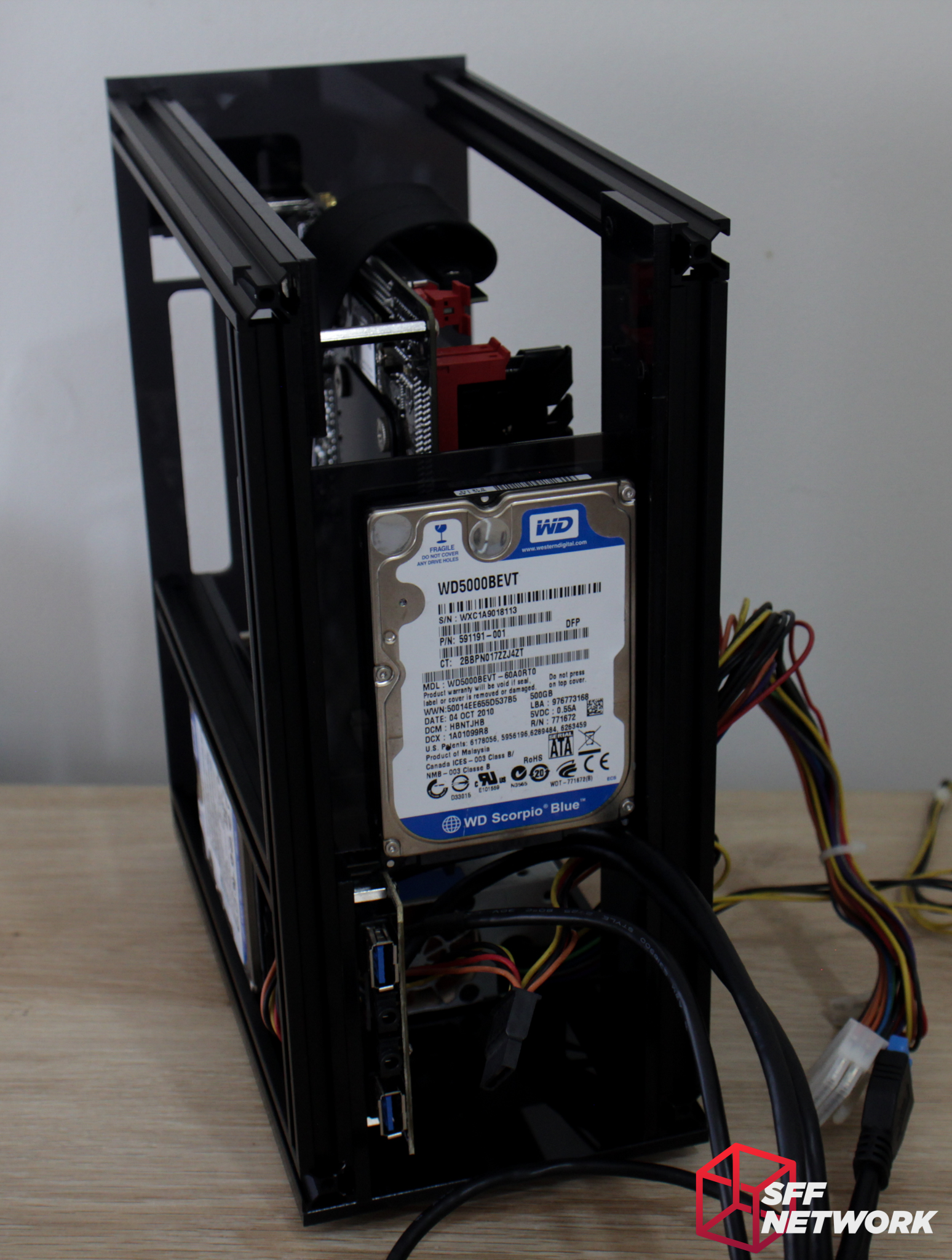
Then mount the panel to the chassis behind the bottom motherboard mount panel. To the front of the case is a cable management hole, which is important as there is no other way for the cables to be routed once the side panel is mounted.
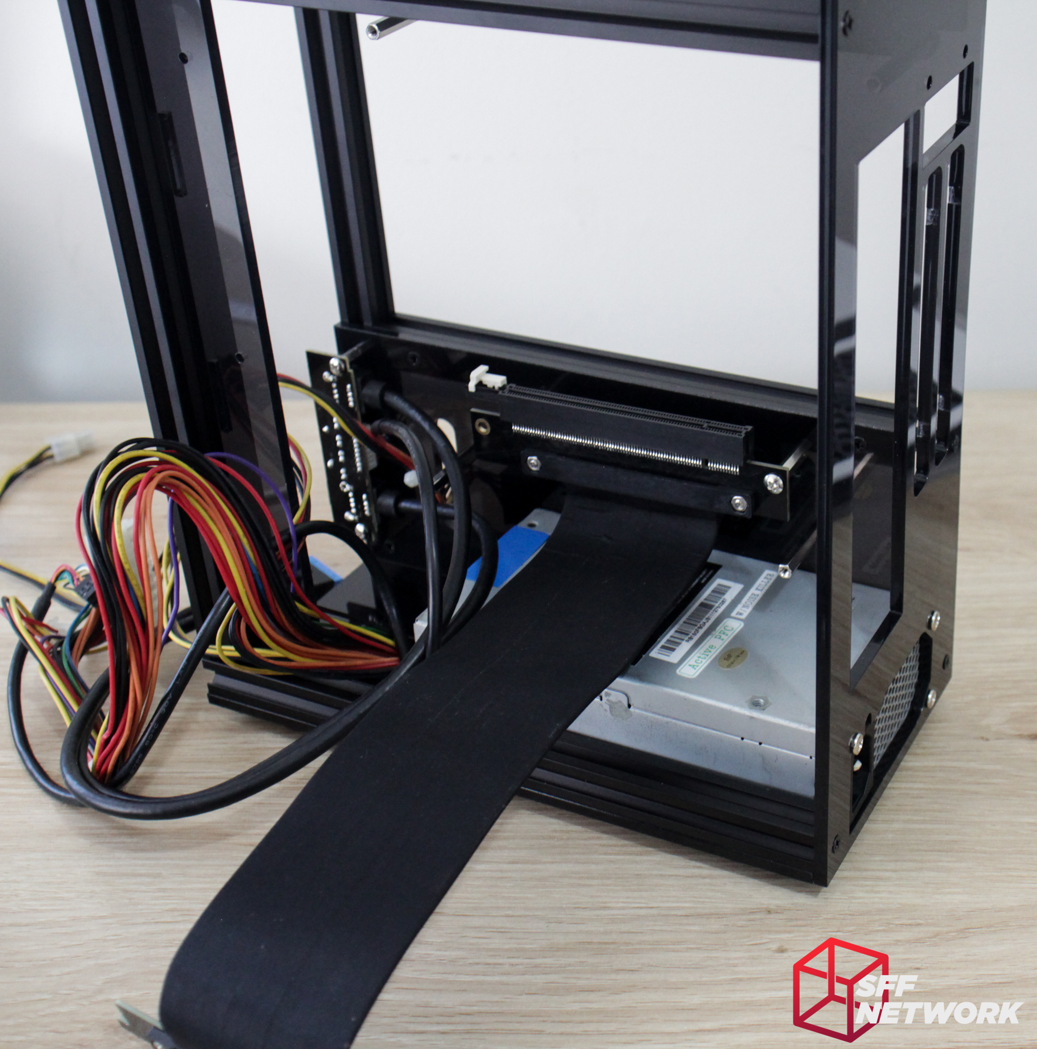
Right, time for the riser install, and my only concerns with the user manual. I went to install the riser to the standoffs we mounted earlier – and oh. It doesn’t fit.

Yup, only one of the standoffs fit to the manufacturer suggested Li-Heat riser.
A view from the back – we’re about 10mm off here.
Let’s fix this. Firstly, remove the riser, then the 2.5″ drive. You also need to remove the aluminium extrusion behind this panel to access the screws fastening the standoffs to the panel. Move the standoffs then re-assemble. Geeek – please note in your user manual which holes are for the riser you optionally bundle with the product!
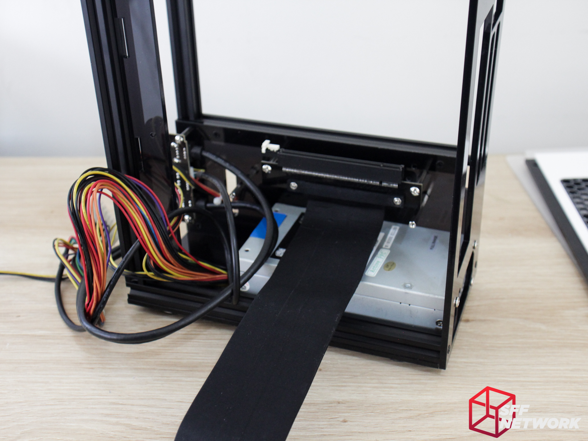
Onwards. With standoffs in the correct spot, the riser fits perfectly. I’d suggest pre-bending the riser – as the Li-Heat riser is robust to the point where casually routing it results in the upper bend pushing against the case fans.
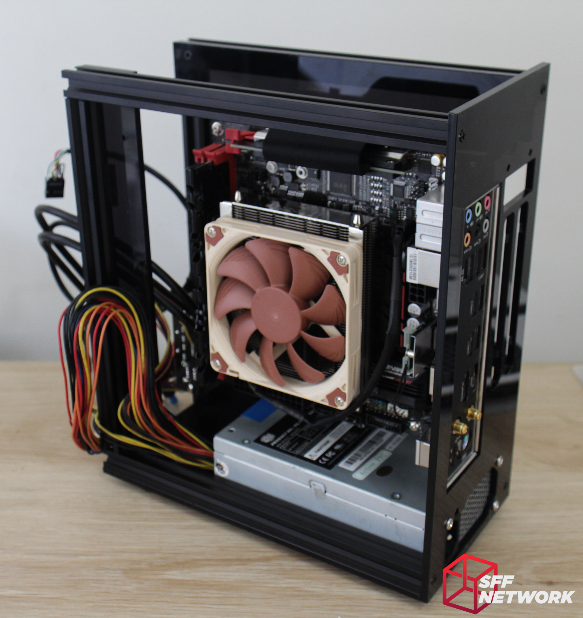
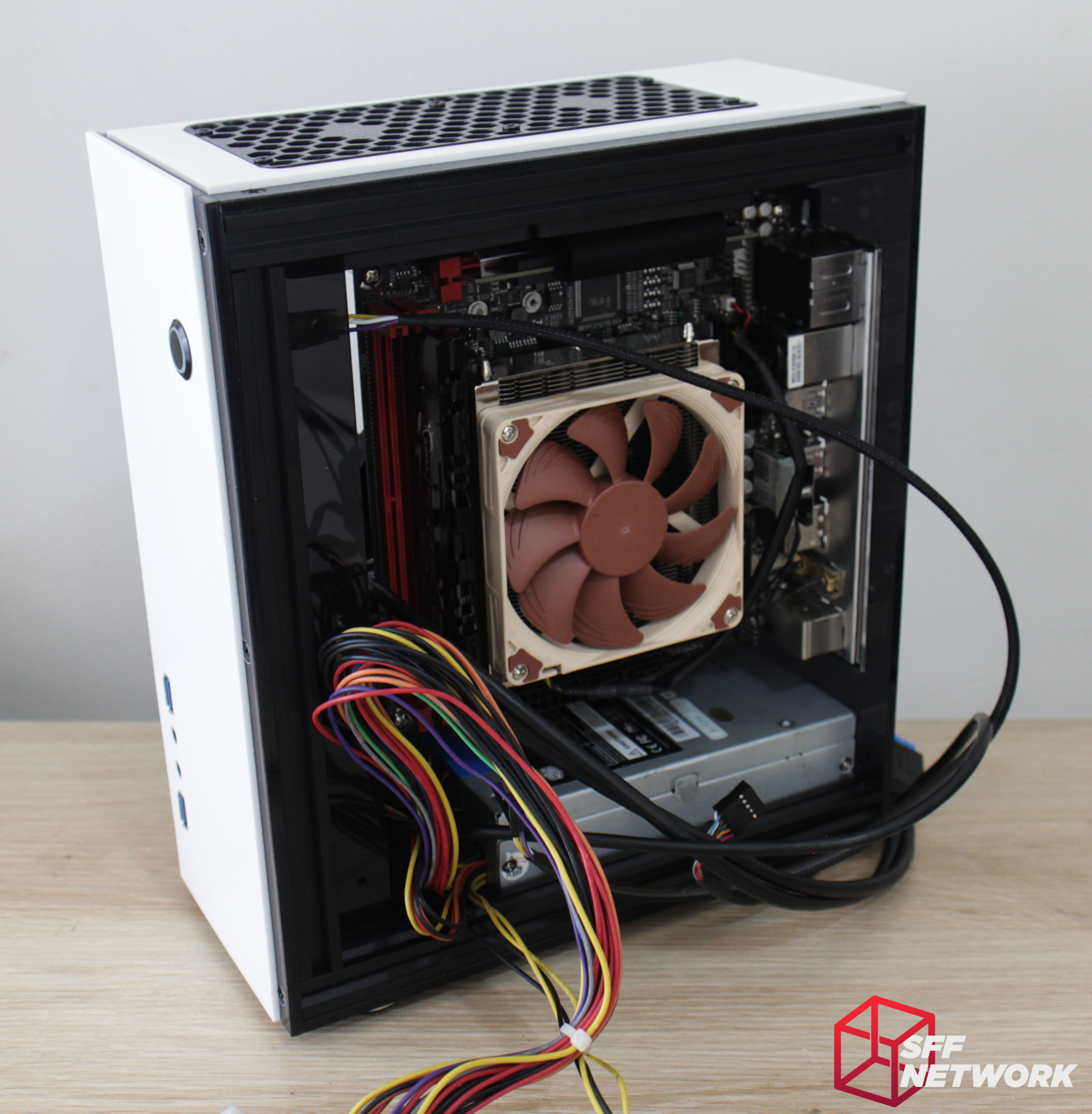
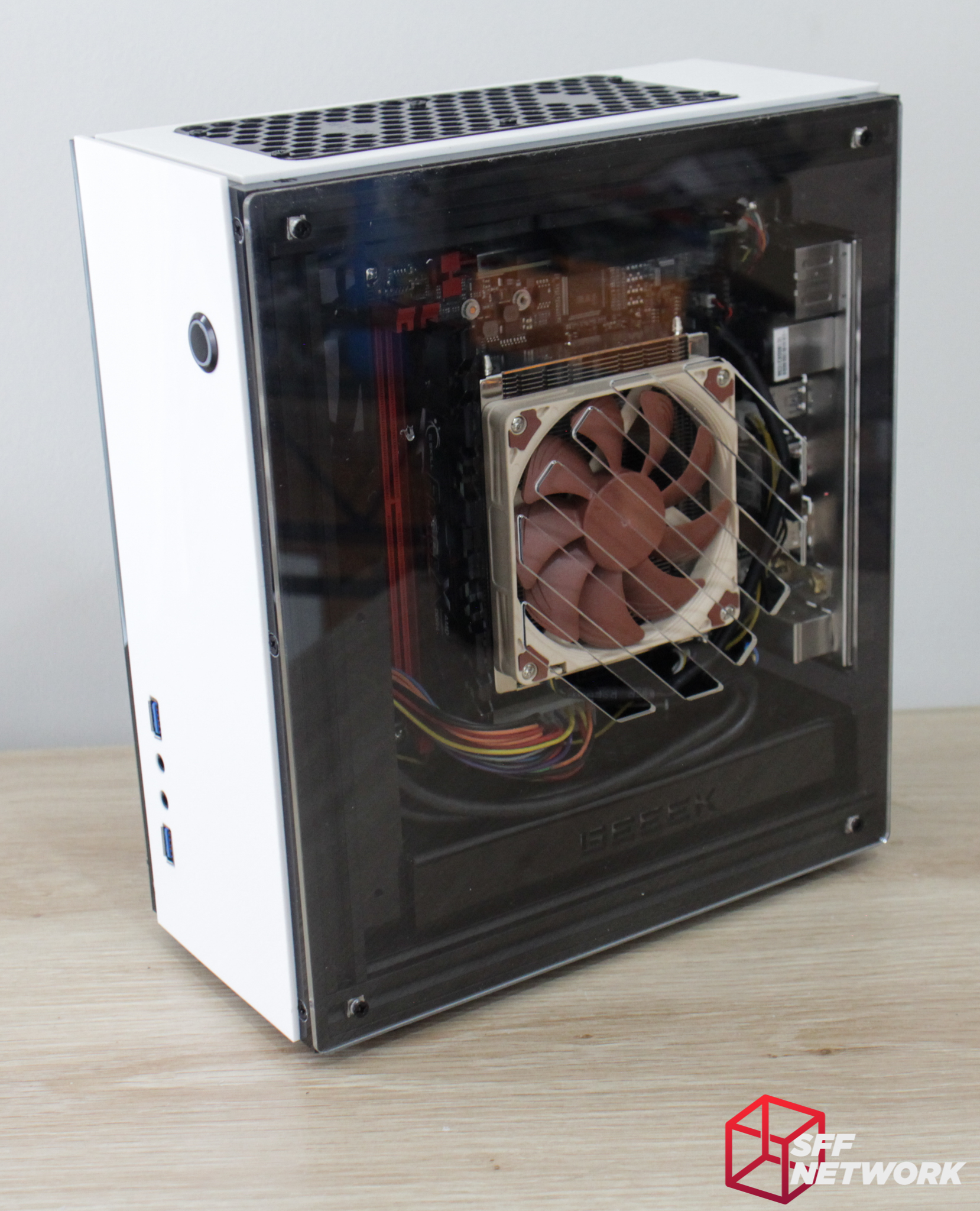
The motherboard makes an appearance and is mounted at this step. Noteworthy is that the IO shield is not held in to the case with a friction fit as in most other cases – it’s relatively loose here and may lead to frustration when subsequently sliding in the motherboard. The CPU cooler must be installed before the motherboard is added to the case – and must be 50mm or shorter.
Unfortunately the riser blocks access to pretty much any M-ITX motherboard’s backplate – so changing CPU cooler may be a rather challenging undertaking.

This mistake is on me, but hey, we’re all human. The GPU retention bracket is mounted (the other way round horizontally) in this step.
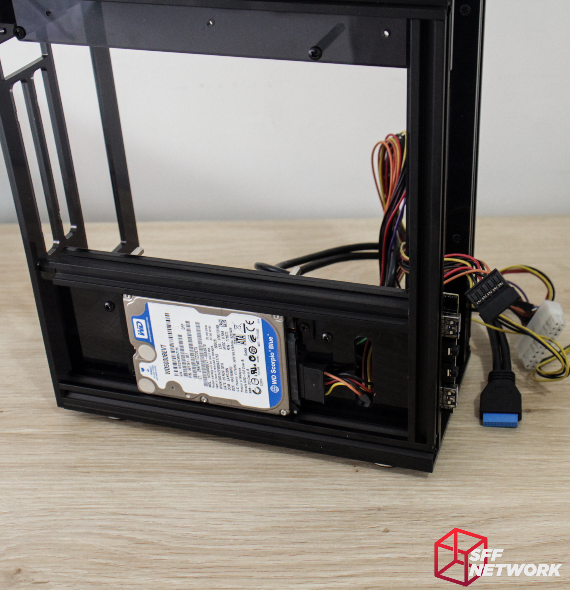
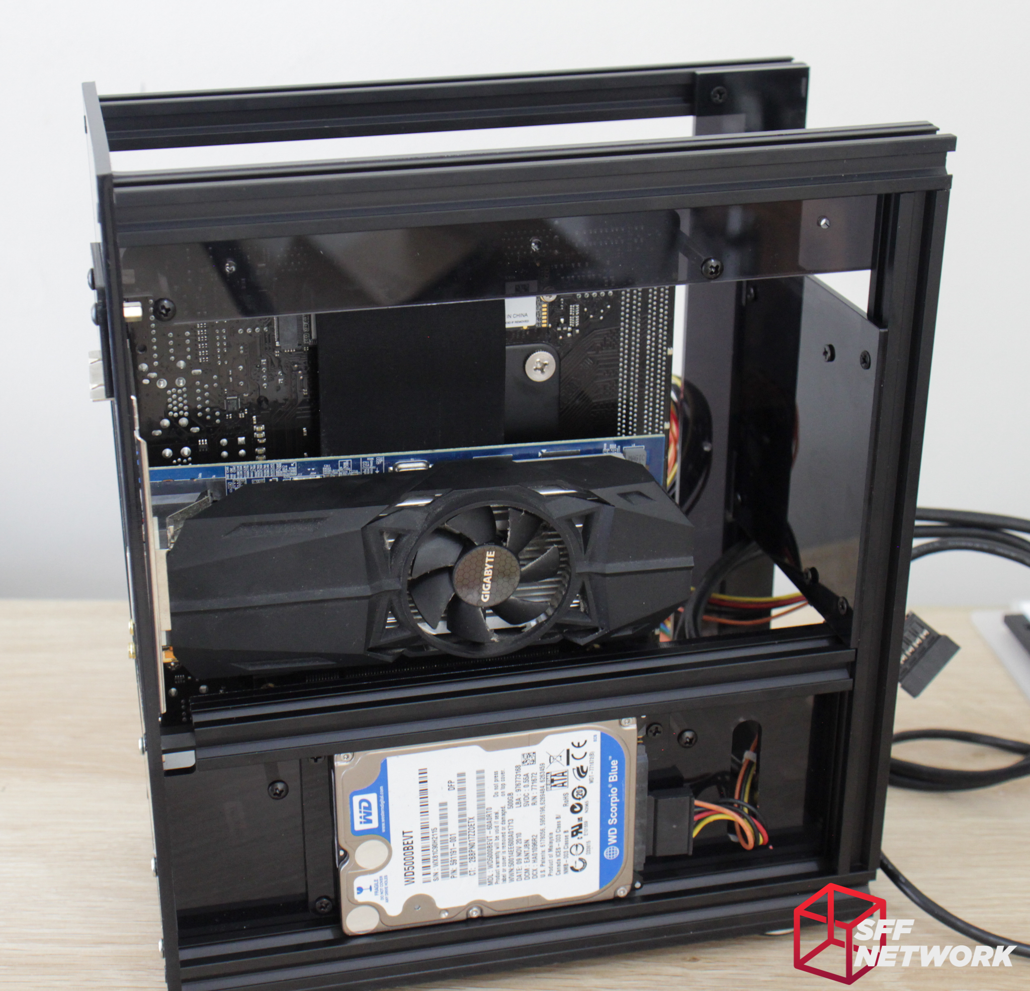
For those wanting a second 2.5″ drive, you can mount it in the front of the chassis now using these parts.
With the drive mounted to the panel, we’re ready for the next step..
Mounting to the inner front of the chassis. Cable management for this drive is understandably less tidy than the other 2.5″ drive.
Slotting in a GPU (in this case a dual slot, low profile card) comes next. The chassis takes GPUs up to 210mm in length, meaning I couldn’t test the chassis with my full-fat R9-270X.

The GPU is then clamped into the chassis. This retention doesn’t provide a lot of confidence to me – even with this retention clip mounted correctly, the GPU still moves around easily.
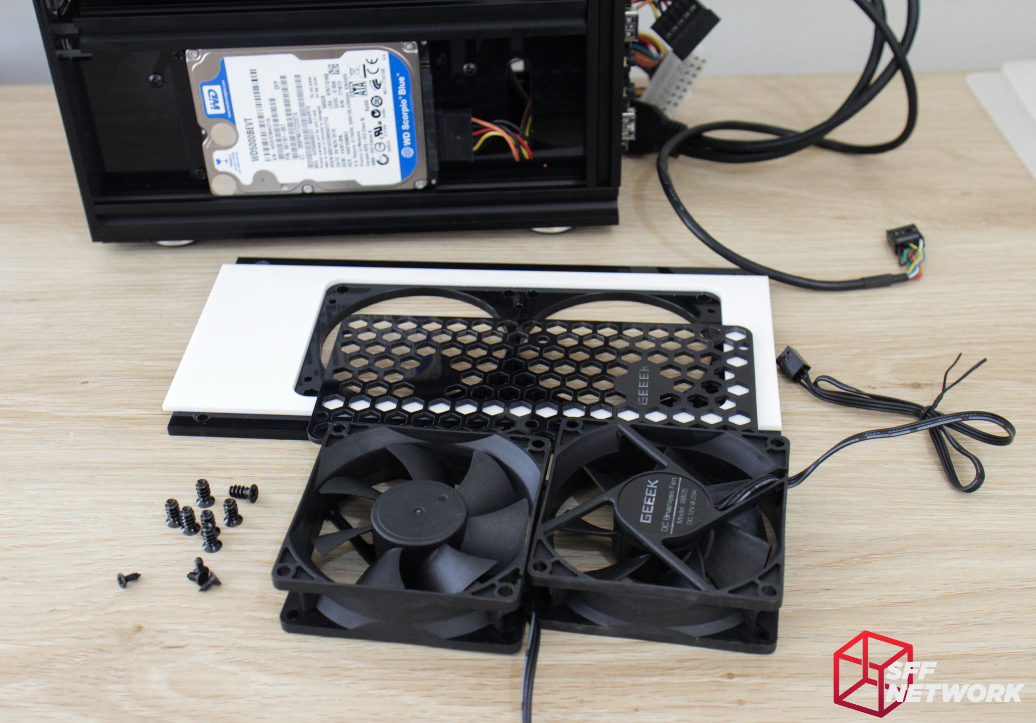
Time to add cooling. These are the two 80mm fans that Geeek supplied. They are 3-pin, voltage controlled units rated at 0.23A. I was unable to find any further information on these fans. With the fan screws and a handful of self-tapping screws provided, let’s get this part together.

Firstly, the fans are attached using normal fan screws.
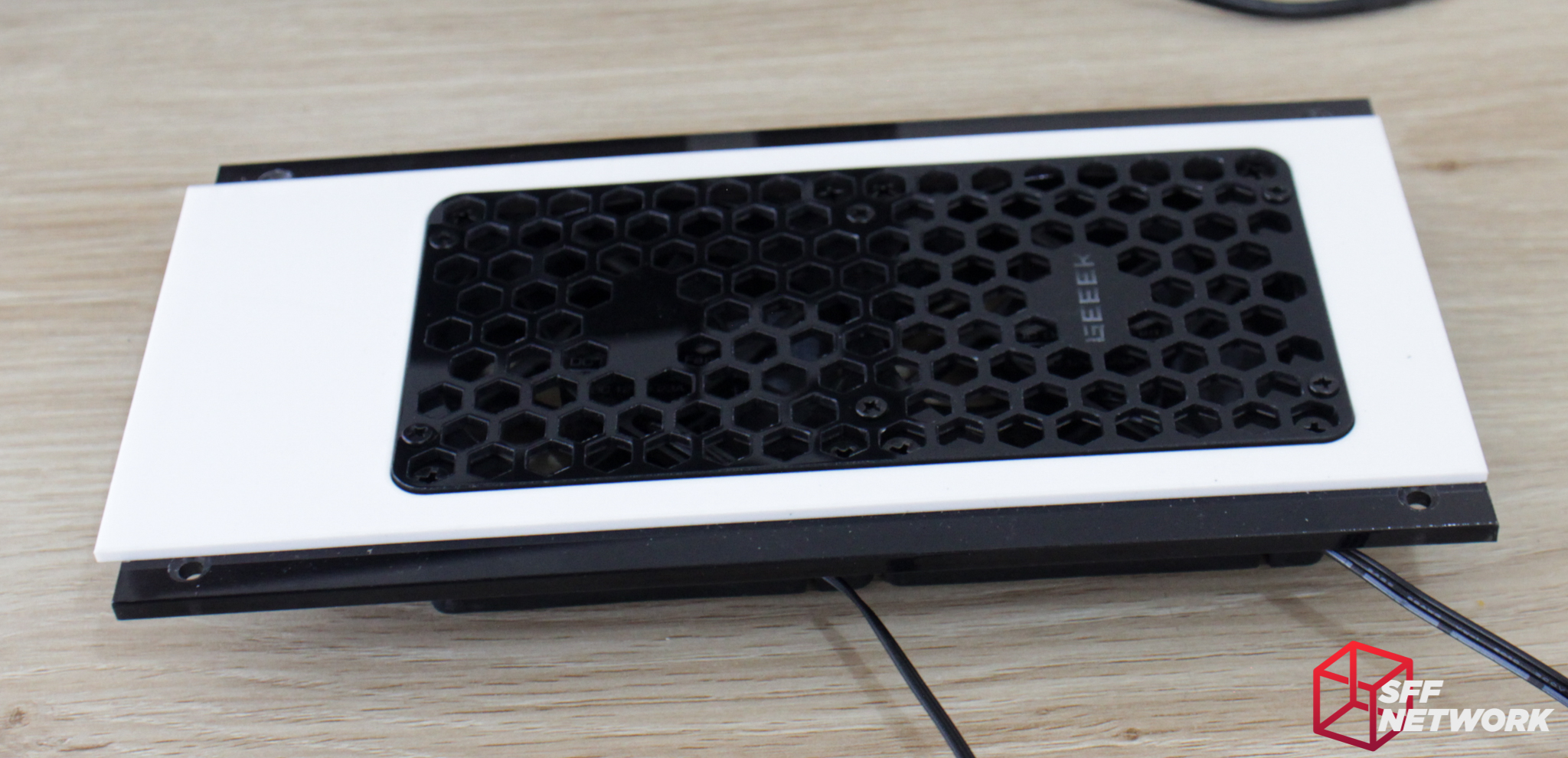
Then the fan grille is attached over top. This does mean that to replace a fan, you will need to remove at minimum 10 screws!
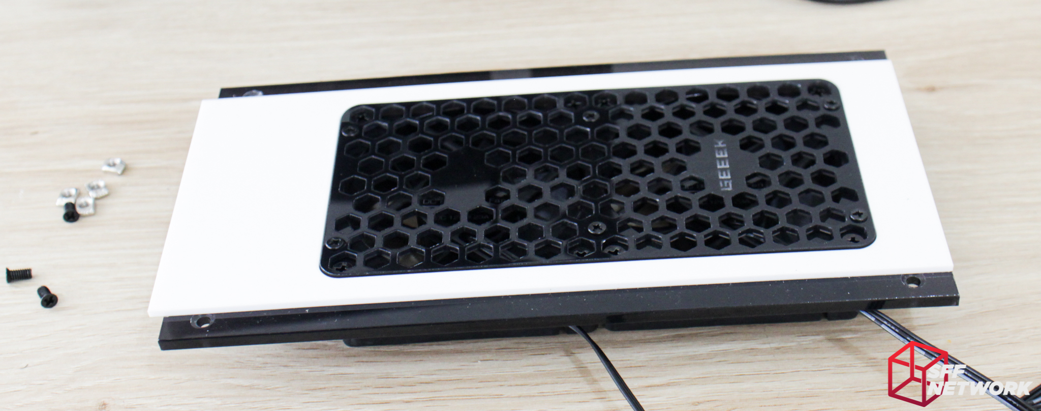
Using the now expected M4 screws and nuts, it’s time to attach this to the case.
And done. The A30 is coming together nicely.
Now for the front panel. the white and smoked acrylic of this panel are pre-bonded, so no need to worry about that step! More M4 screws and nuts are used to mount this to the chassis.
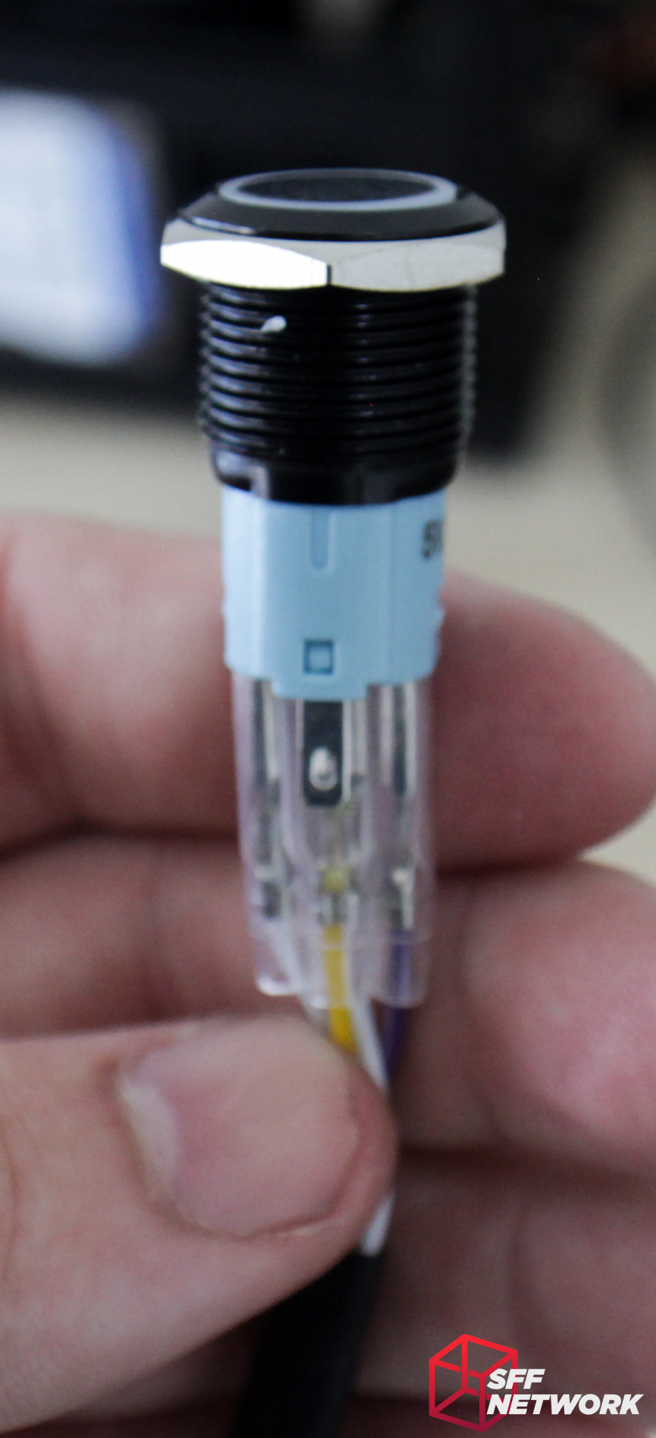
Of note is the black vandal-resistant power button included with the case. This switch feels of high quality construction, with all connections made using spade terminals rather than the usual soldering, a nice touch.
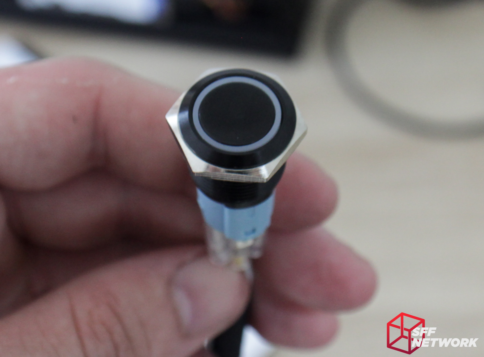
The switch is rather deep for a vandal-resistant switch, however, this does mean the button has a deeper press, and is thus resistant to accidental presses.
Throwing all of this together means the core chassis is done.
The power switch cable is very long, so may present some routing challenges – there will be a lot of excess cable to hide. Speaking of hiding cables, most of the spare room for excess cable is in the front of the chassis, so let’s get this all wired up.

With the PSU cover in place (it is held to the Flex-ATX PSU with two strip magnets), the build looks somewhat decent, given the non-sleeved nature of my PSU.
Minus a SATA data cable, the GPU side is done! Some excess cable has made it’s way over here. Without cable ties, this is inevitable though.
Yep, I still haven’t fixed that GPU retention bracket..
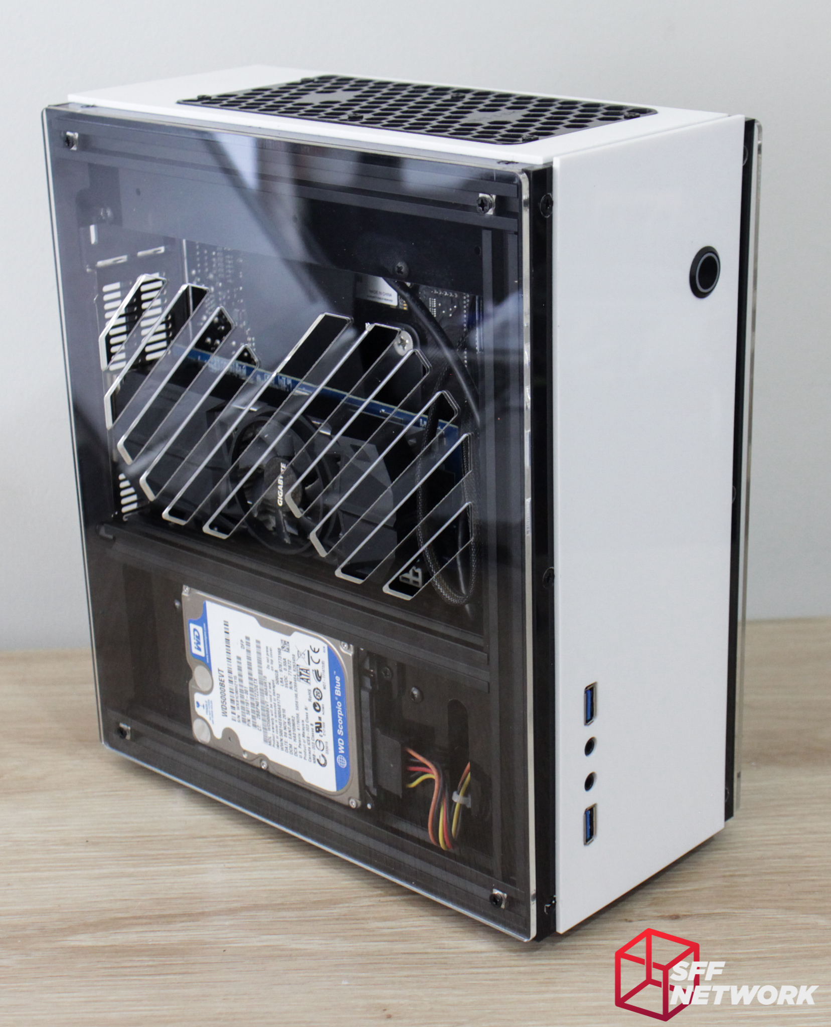
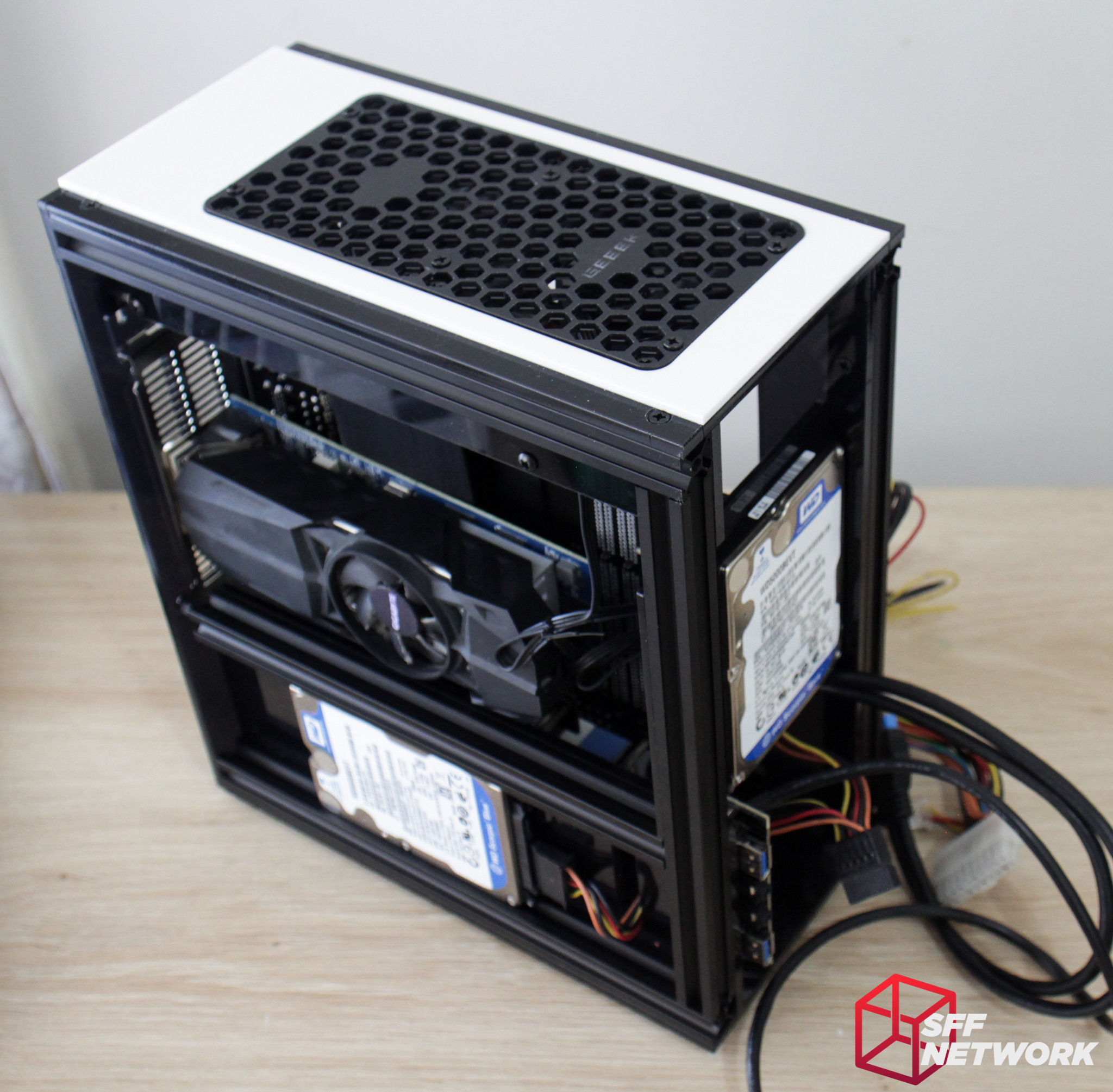
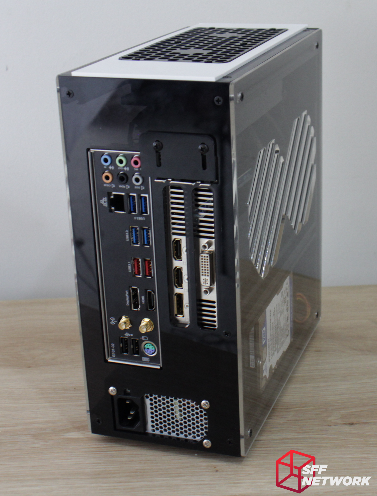
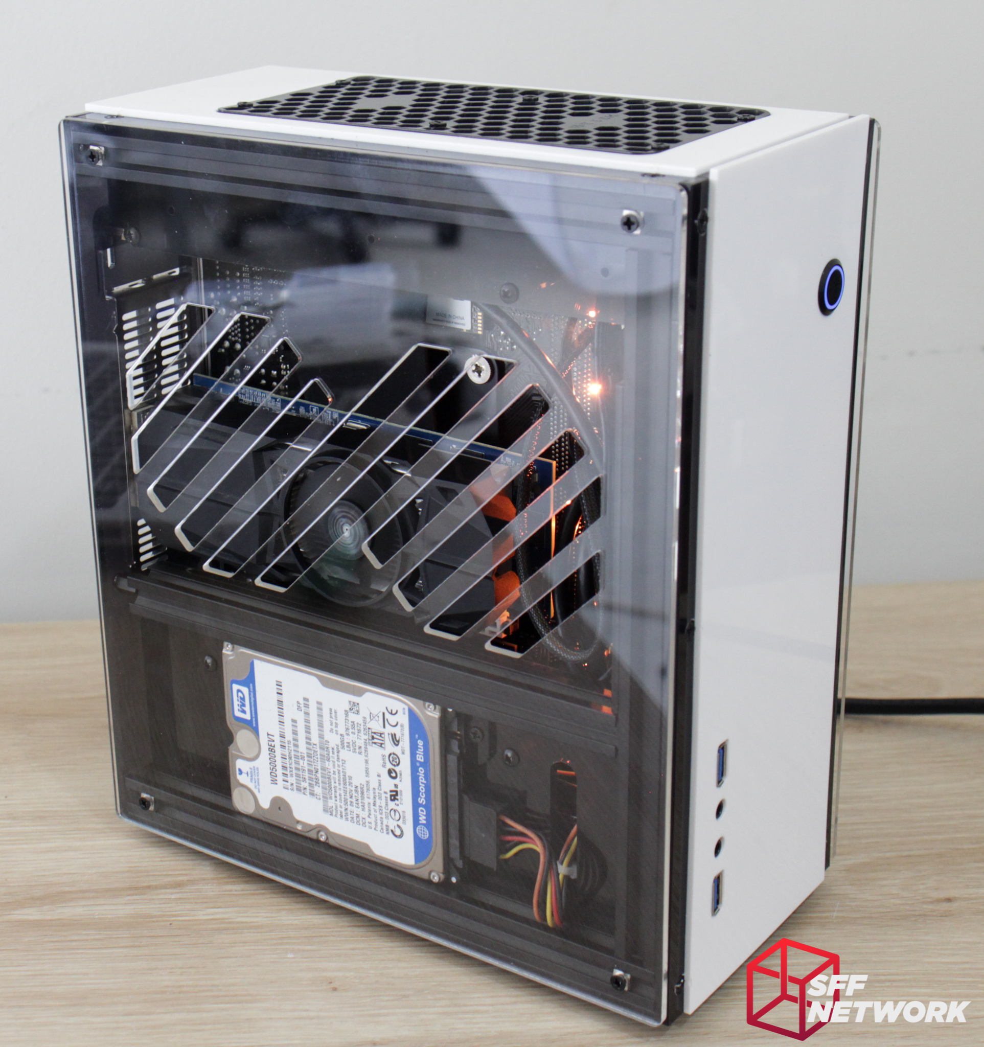
The side panels mount with four of the M4 screws and nuts, completing the chassis. The two side panels are different in their design, with this side having a more GPU friendly cutout layout.
The panels are flush with the grey acrylic portion of the top and front panels, meaning that the mounting screws for those panels will remain visible.

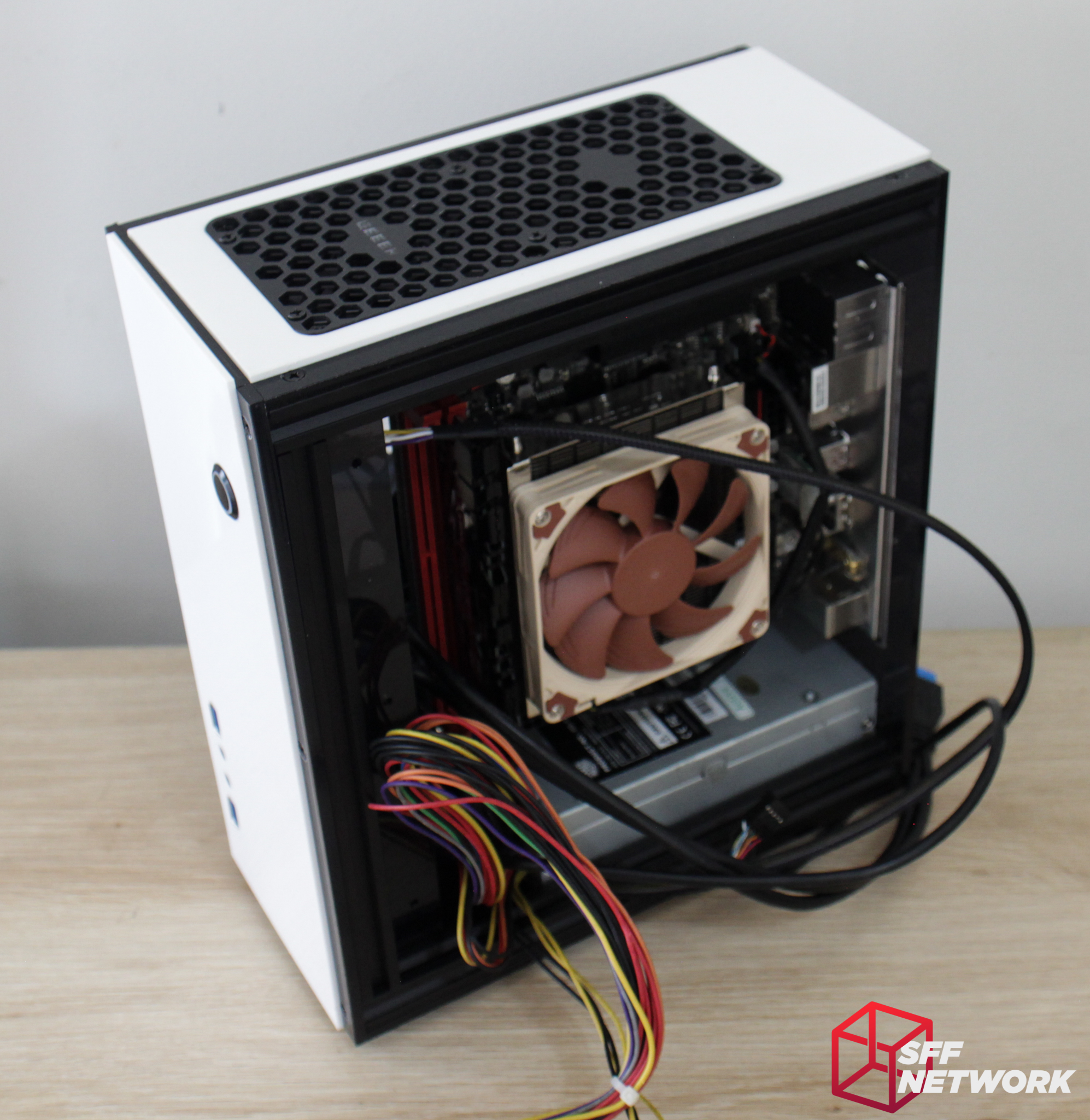
The motherboard side panel has a single fan styled vent pattern, more appropriate for this position.
Glamour shot!
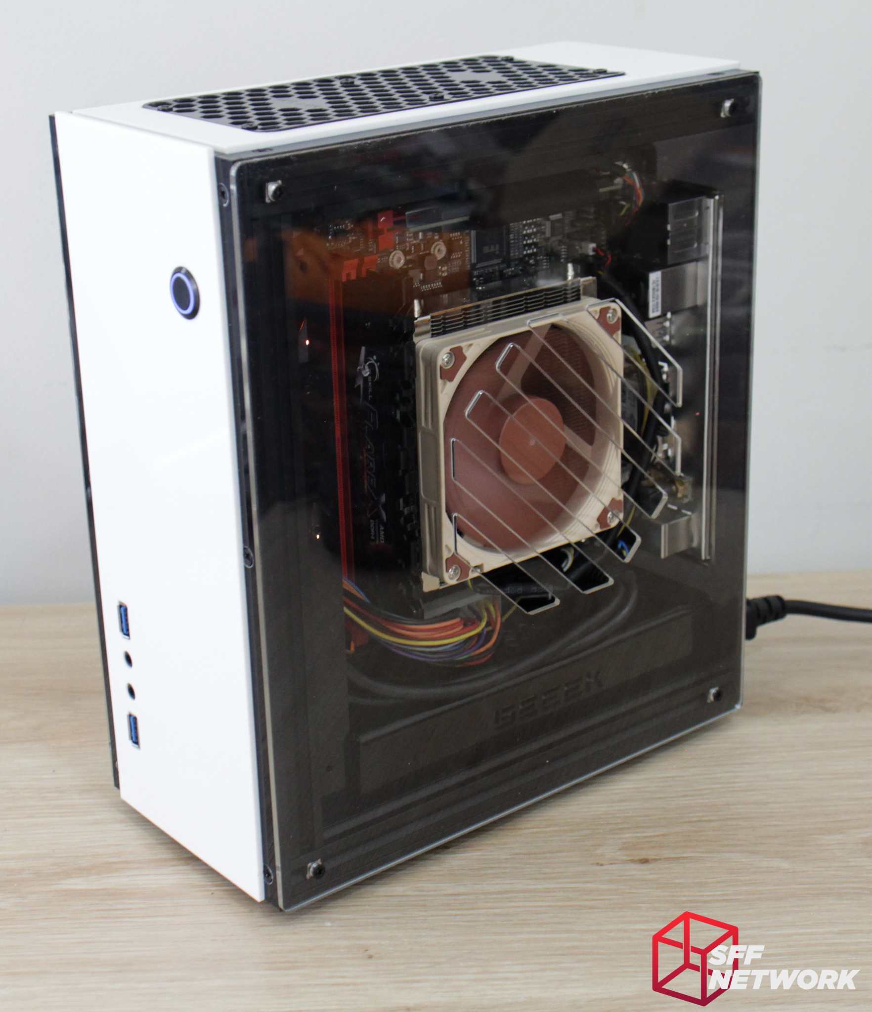
It verks! The vandal resistant switch glows a satisfyingly subtle diffused blue.
The only RGB in the chassis is part of the motherboard!
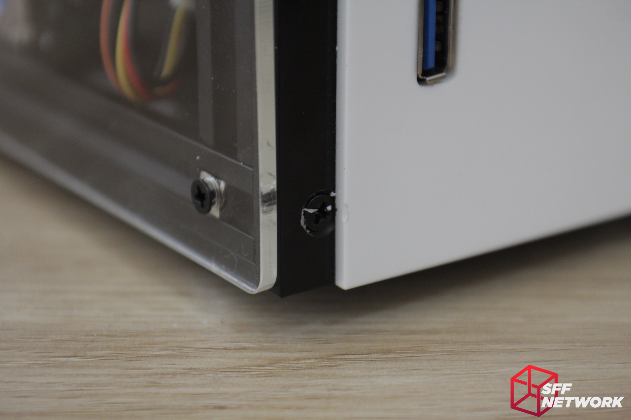
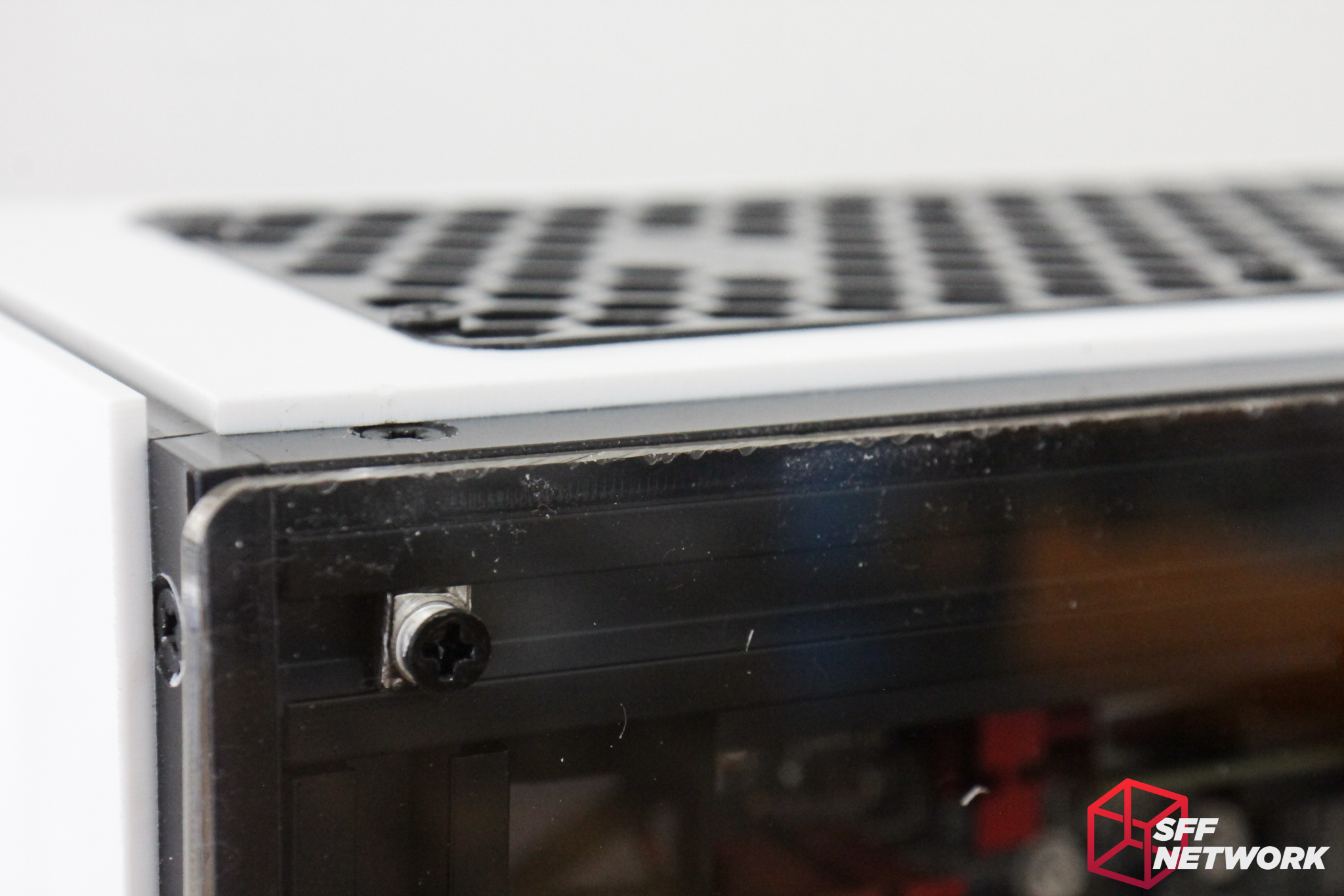
Unfortunately some design aspects aren’t ideal. The screws mounting the top and front panels are partly obscured by the white acrylic, meaning that rotating these (and even the act of installing them) can mar the finish of the panels.
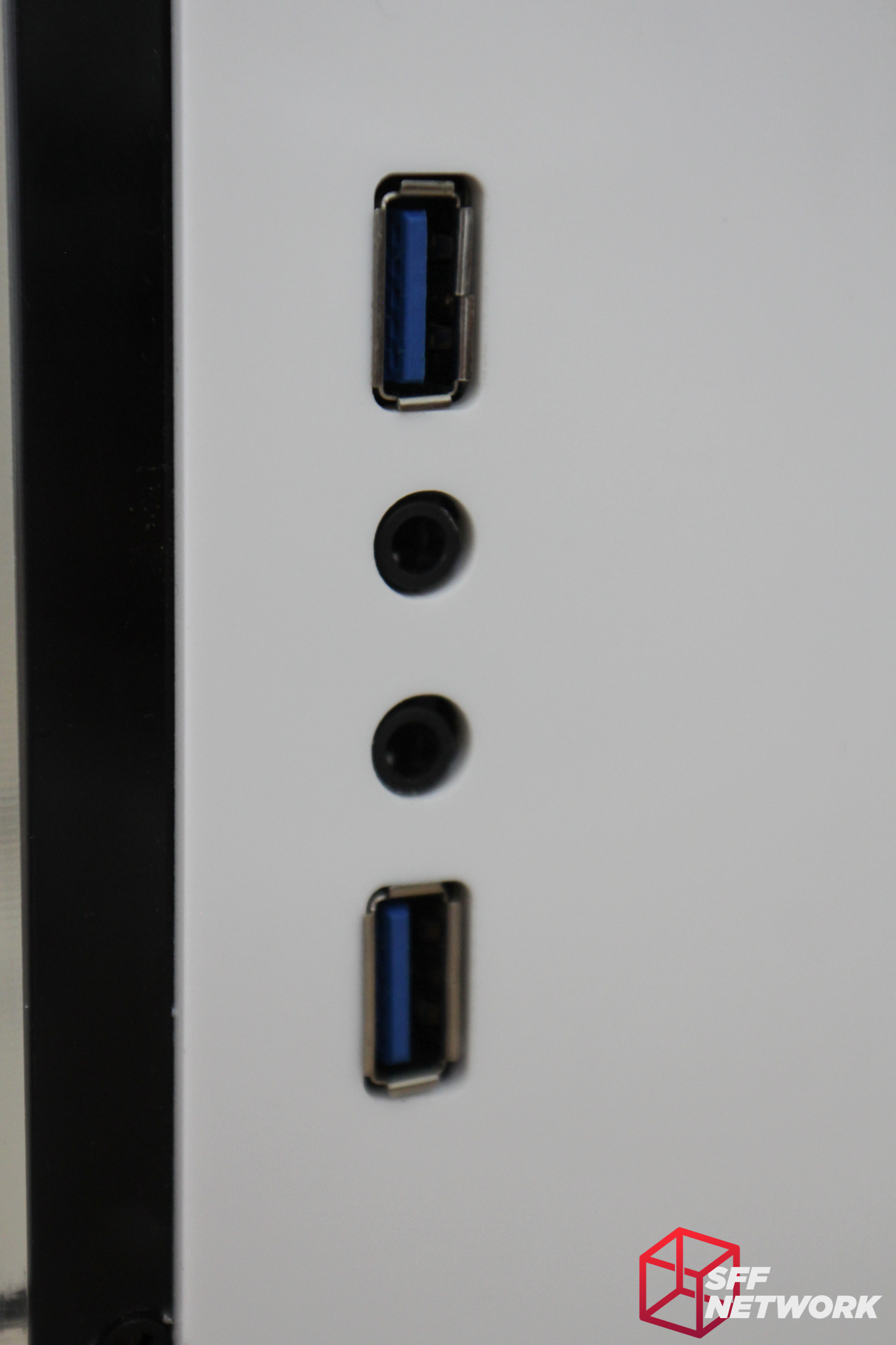
The front panel IO cutouts are appropriately sized.
A closeup of that M4 screw and nut mounting setup. The nut rotates around and locks itself into the groove in the aluminium extrusion. This is easily reversible on removing the screw.
The top and front panels don’t meet up, something that some may not find aesthetically pleasing. Also of note here is another example of the partly obscured mounting screws leading to damaged acrylic.
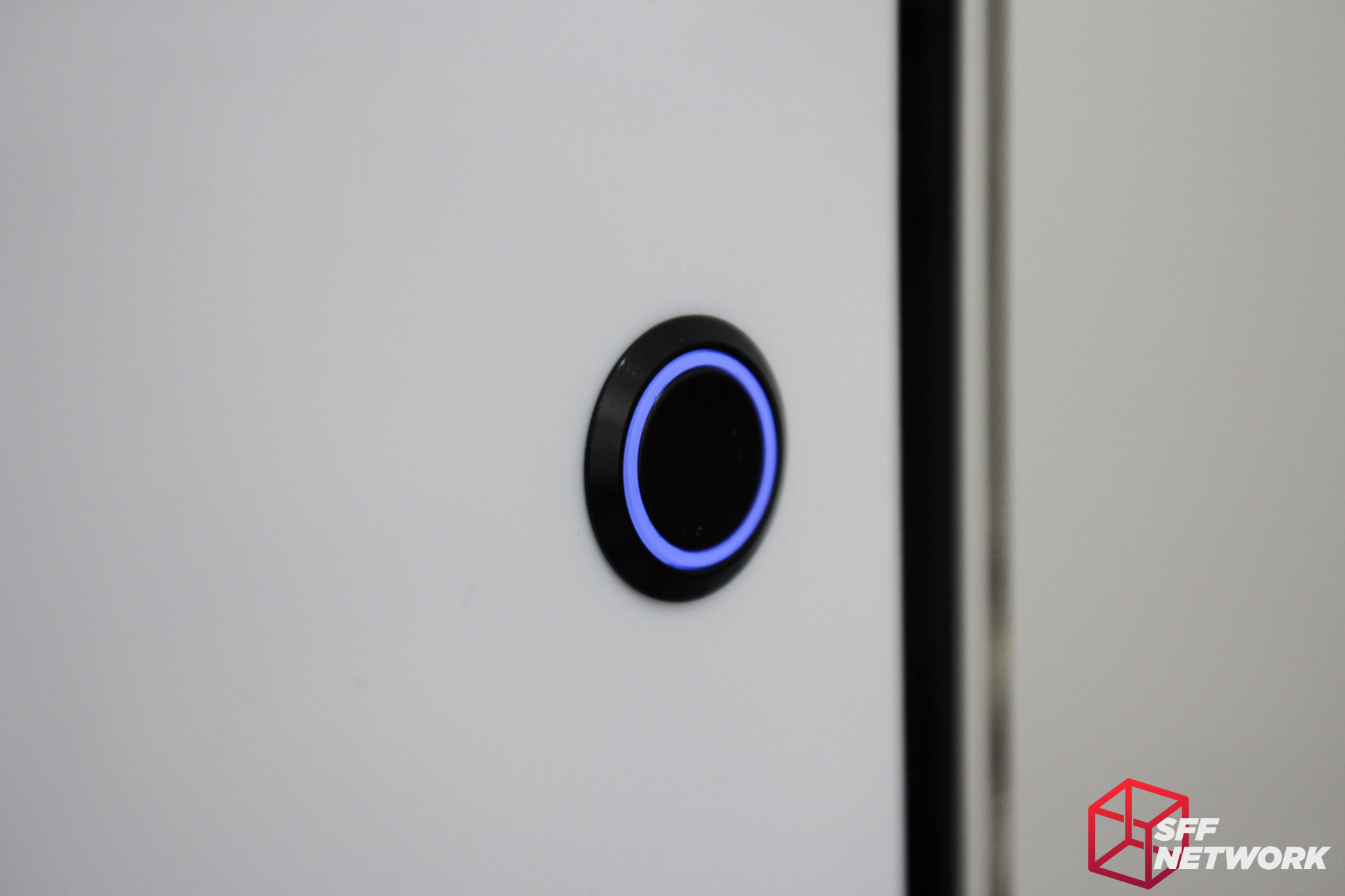
That subtle, diffused blue glow. Much, much, MUCH better than the typical blinding blue of traditional switches.
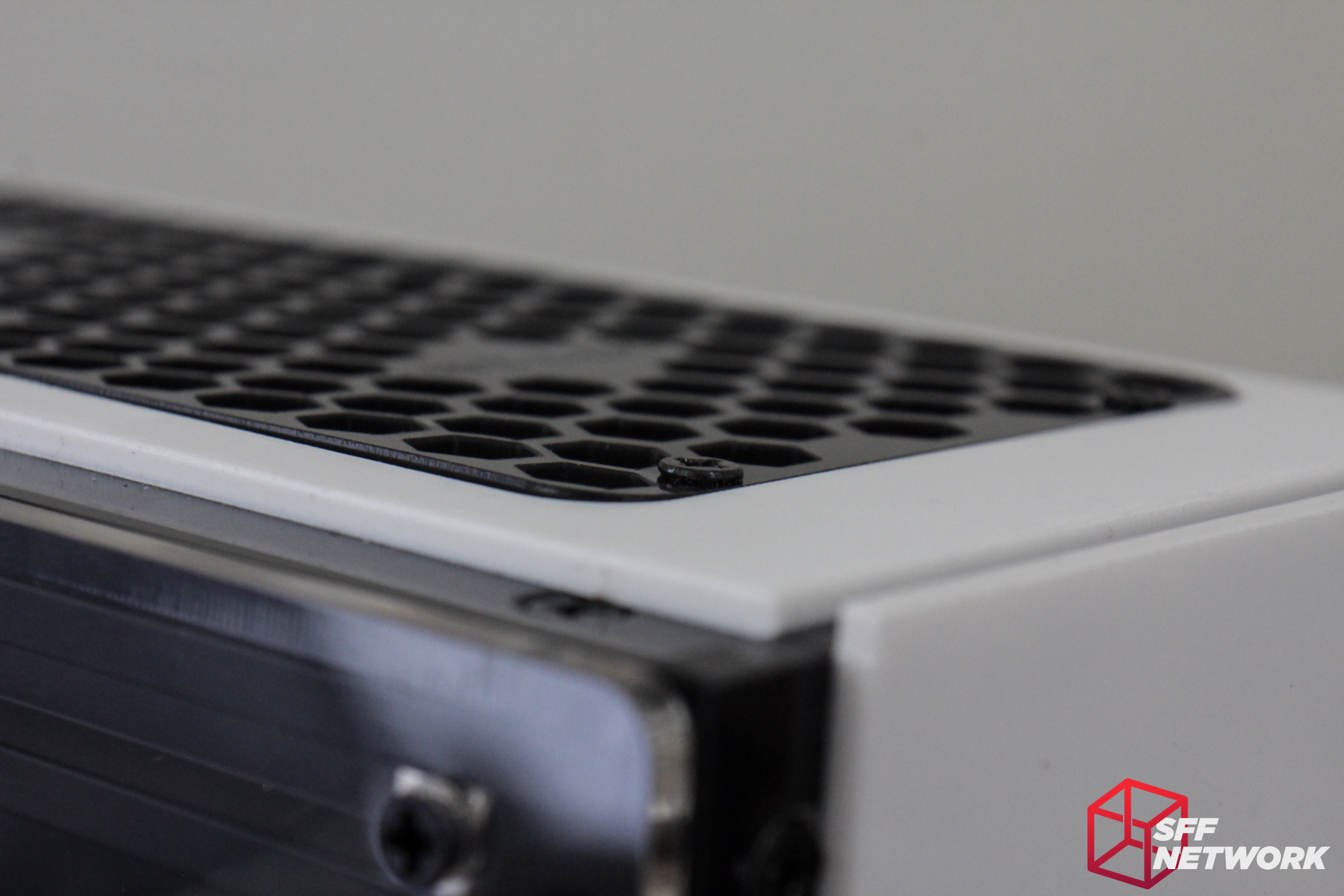
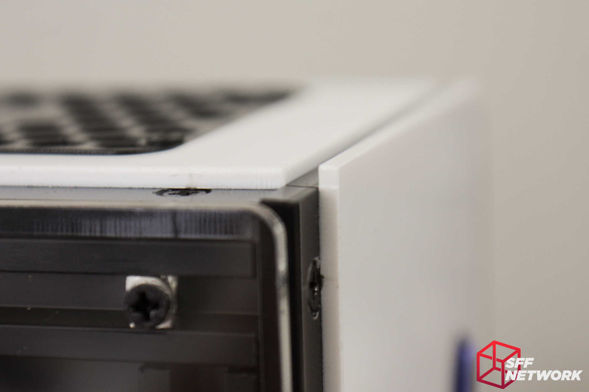
Unfortunately the design of the top panel leads to the mounting screws protruding once the panel is installed.

All 6 screws holding down the fan grille suffer from this. A countersunk hole for each of these screws would have gone a long way to smoothing out the lines of the chassis.
This edge of the motherboard side panel was pretty rough, but this may be only an issue on my unit, rather than an outright design flaw.
The PSU shroud really adds a nice touch to the design and look of the build – I’d recommend anyone buying an A30 to add this to their purchase. I do wish Geeek would add an unbranded option though.
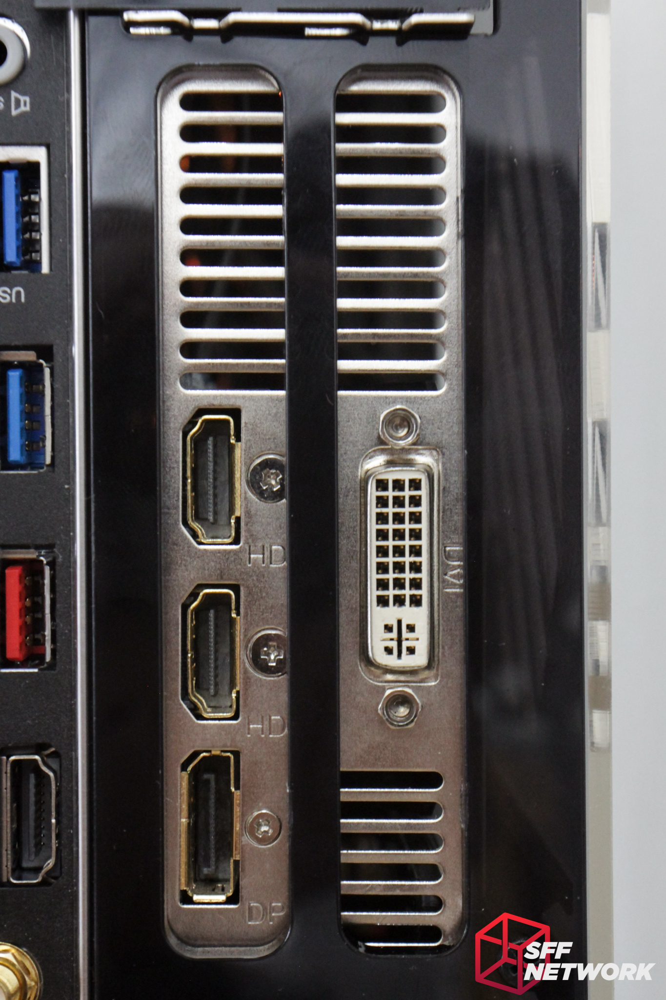
The cutouts for the GPU are well placed and did not obscure the ports of any card I installed. (I’ve come across this issue in steel and aluminium chassis from well known brand names before!)
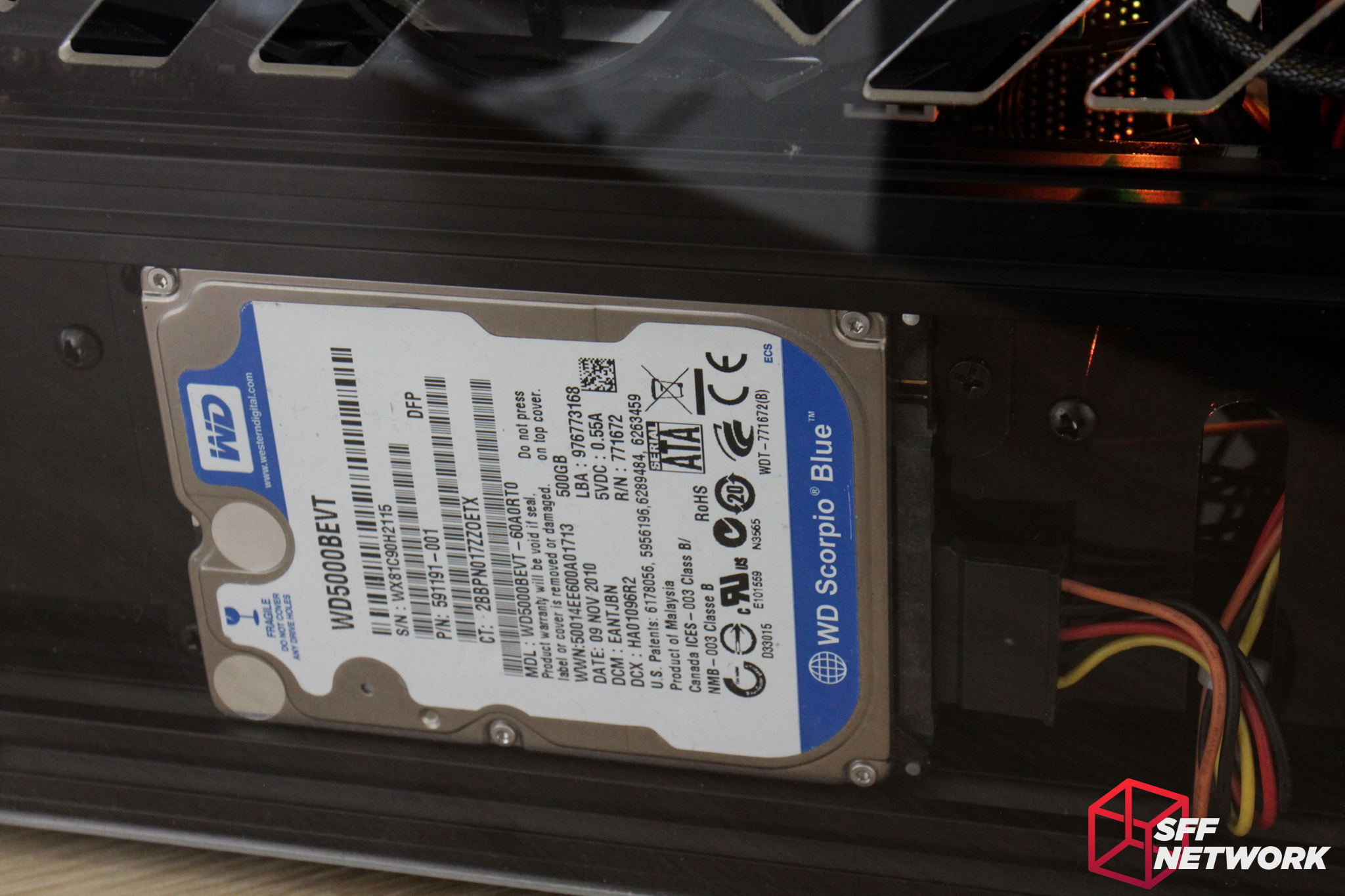
I hope whatever 2.5″ drive you install (if any) is a good looker – it’s on full display!

Ample cooling should be available for the GPU – it’s a little overkill for my GTX750TI LP though!
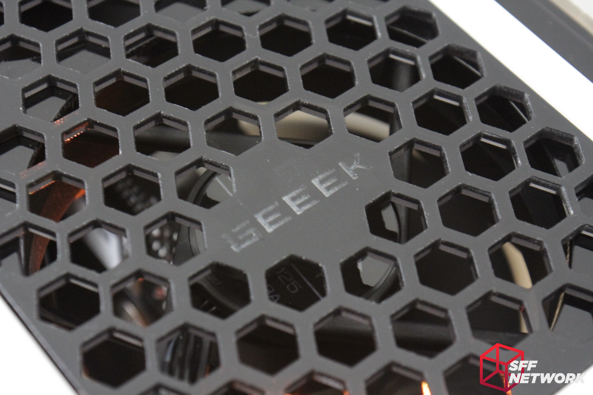
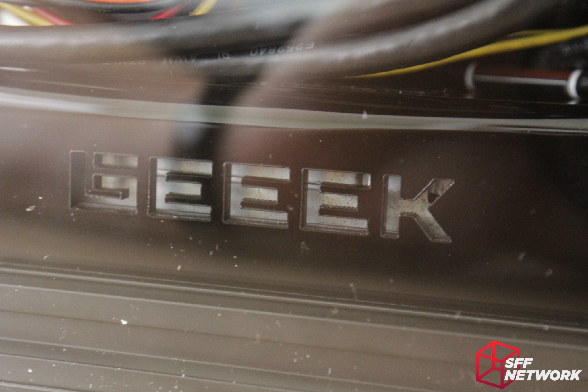
The Geeek logo is etched into the fan grille, but is patchy if not 100% clean.

This is where the sins of cable management hide – the front of the chassis.
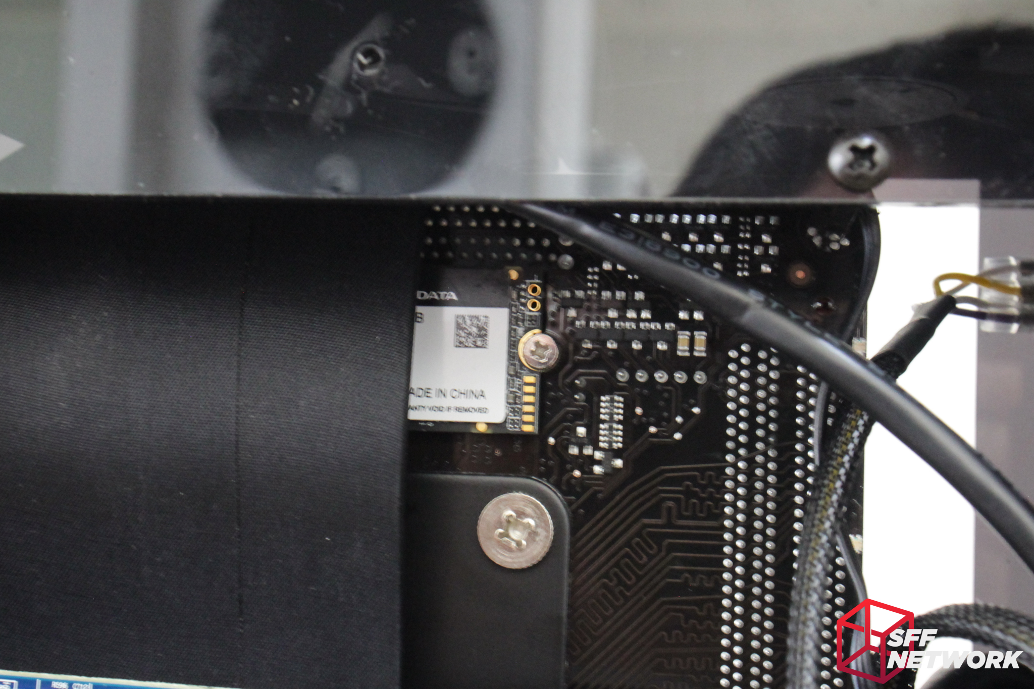
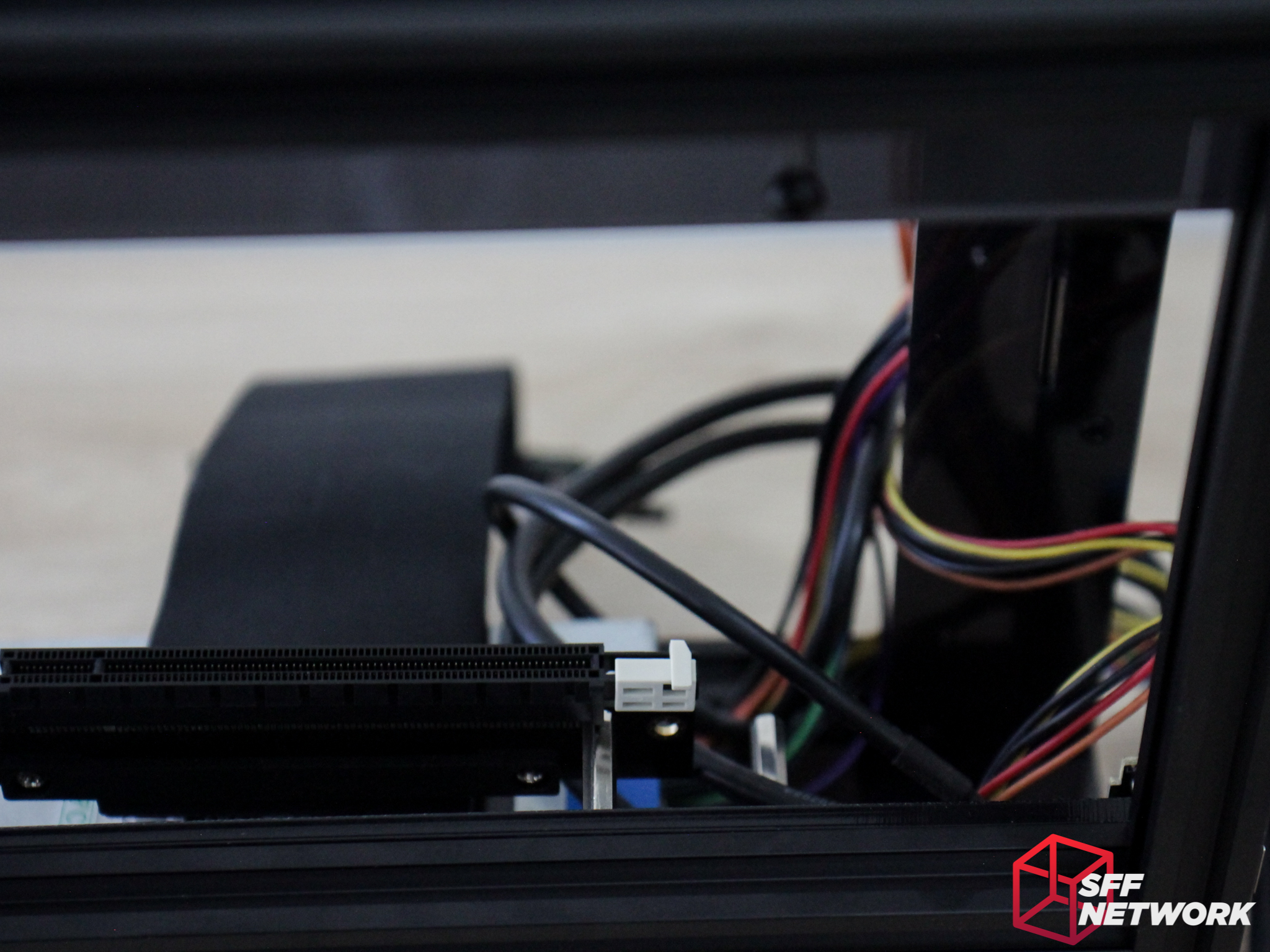
Alas, even the M.2 position on the Gigabyte AB350N-Gaming WiFi is obscured by the PCIe riser, but this is a tradeoff of this particular layout.
The Testing
To test the chassis (apart from the build up process), we threw in the following hardware;
| CPU | AMD Ryzen 5 1700x |
| Motherboard | Gigabyte AB350N-Gaming Wifi |
| RAM | G-Skill FlareX 8GB |
| CPU Cooler | Noctua NH-L9A-AM4 |
| Power Supply | Cooler Master 150W Flex-ATX |
| GPU | Gigabyte GTX 750TI OC LP |
| OS | Windows 10 Pro 64 Bit |
| Thermal Monitoring | Gigabyte System Info |
| Thermal Load | Prime 95 Blend |
To test the chassis, we booted it with the above system installed. First, we let the system idle for ten minutes, ensuring any post-boot processes have completed and the system is truly idle. At this time, the temperature of the system (in this case, CPU and Chipset temperatures) is recorded, as well as the ambient temperature in the room. From these, we get the delta temperature – in other words, the temperature difference. Reporting a temperature difference rather than an outright temperature is, in our opinion, a more useful result. This is due to the nature of our environments – some readers may have an ambient temperature in the low 30’s, and some in the single digits – the maximum temperature of the system would change between these two environments, but the delta would be the same (well, mostly, but that’s delving into physics, and we don’t have time for that!).
Once the idle temperatures are recorded, Prime95’s blend mode is started, maxing out the CPU and RAM, pumping as much heat into the chassis as possible. Some may note that we did not load the GPU in this scenario – unfortunately due to my hardware stocks only having the low power GTX750Ti available to me (I have higher end hardware but they would not fit in the A30!), I felt that the results and additional heat wouldn’t be worth the time invested. After the system hits a thermal maximum, it is left in this state for 10 minutes, and the average temperatures over this time is recorded, and once again, compared to the ambient to record the delta.
Note that above, we did not mess with fan speeds – in fact, the above portion of testing is done under the normal fan presets that come preset in software and BIOS, which is the most likely use-case for end users. Now we get into the less relateable information – max fan speeds. All fans in the chassis (including CPU cooler, chassis and PSU fans where possible) are set to maximum speed. Once again, an average is taken once the system stabilises. Finally, the load is removed, and the system is left to idle, with the fans still at maximum,. Once a stable temperature is reached in this mode, the system is once again left for ten minutes, and an average taken.
The Results
Throughout testing, the ambient temperature in the room was 25 degrees Celsius (I really wish my landlord would install air conditioning!).
Under idle, the CPU reported 15 degrees above ambient, with the chipset at 40 degrees above ambient. This is to be expected, as we are running a 95 watt CPU, with a very low profile cooler. The chipset also sits in somewhat of a dead spot for air in this particular chassis design. Under full fan speed, these temperatures reduced to 13 degrees and 33 degrees above ambient respectively. The extra airflow from the CPU cooler at full fan speed really does help the chipset here.
When the system is loaded, we see 35 degrees delta for the CPU, and again, 40 degrees for the chipset. These results are within the approved thermal envelopes for the hardware, so no issues here! I cranked the fans up to maximum, which didn’t change the temperatures – reinforcing my understanding that the system was running at maximum fan speeds at load.
However, even with the “small” 80 mm case fans and 92 mm CPU cooler, the system was not overly loud. Whilst it was indeed louder than my performance focused NCase M1 personal system, the system still was within comfortable aural levels under load. At idle, the system was as quiet as is to be expected! Note that we were unable to record actual decibel readings for this system – I do not as yet own a dB meter.
The Conclusion
So, this is the second Geeek chassis we have tested, has Geeek continued to grow and develop their products? In my opinion, very much yes. The Geeek A30 is leagues ahead of the A10 we tested in build quality, design considerations and overall specification. The designer has taken into account many smaller design aspects that even larger case manufacturers fail to implement – from easy to remove panels, modular design, to even more basic aspects such as ample cable management room in the design.
All is not rosy, however, as there are more than a few sore points in the design and documentation. Missing information for mounting points for optional hardware – having to tear down part of the case to fix the PCIe riser mounting – was frustrating to say the least. Also missing was instructions for the 3.5″ drive mounting! Alongside the informational issues, we also have a few build issues in regards to physical design – screws that stick out, and a loose GPU retention mechanism are aspects of this.
It’s important to take into account the price of the product alongside the positives and negatives. The Geeek A30 sits in the cheaper end of the small volume production SFF chassis market, for which I applaud them. We all get excited over the likes of the NCase M1, the S4M, and the like, but they cost upwards of 4 times the price of the Geeek A30! Selling an acrylic chassis at this price level is a remarkable feat in my opinion.
Do I recommend the Geeek A30? Yes and No. If you’re looking for perfection or high performance, it isn’t here. If you are looking at cheap but capable SFF cases, with customisation capacity and a unique look, the A30 may be worthy of your shortlist.
Pros
- Great price
- Unique look
- Quality hardware included (I love the vandal resistant switch that Geeek included!)
- Compatible with a good selection of components for the size
- Flatpack!
Cons
- Building issues and documentation issues as noted in the conclusion
- Moderate cooling capacity due to lower CPU cooler headroom
Nitpicks
- A little tighter grip on the IO shield would be good during the build phase
- Option for USB3 Type C front IO panel
Thoughts? Discuss them in the forum!