Prototype A DIY kit - making custom cases easier and more approachable

Shatrod

Airflow Optimizer
Gold Supporter
Dec 6, 2019
236
394
redshiftproject.com
Hey Everyone.

I see all sorts of custom cases and one off designs now with the advent of 3d printing. And, at least in my experience designing a case is actually quite hard. Reading all the specs for the motherboard, the keep-out regions, figuring out how to mount the gpu reliably, and designing around all of those mechanical constraints of the form factors is a significant challenge, especially for people relatively new. So, i set out to try and make this a bit easier to make case design more approachable, especially for first timers. The goal isnt to make the smallest or densest case with this, but rather to allow people to get their feet wet, make something, and worry more about designing the actual case part and making it look good instead of all the pcie-sig and atx specs.

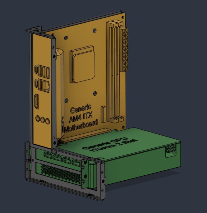
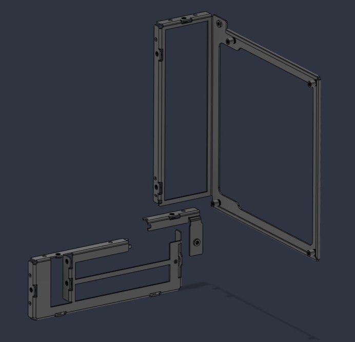
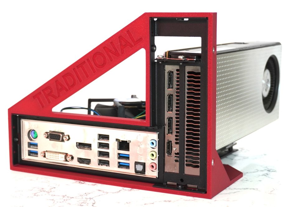
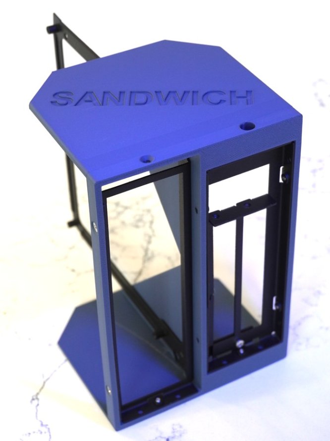
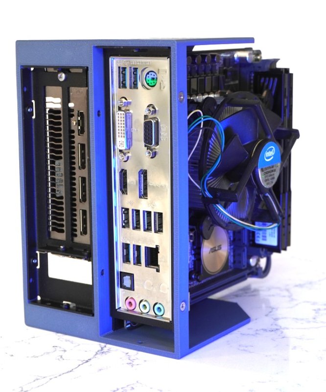
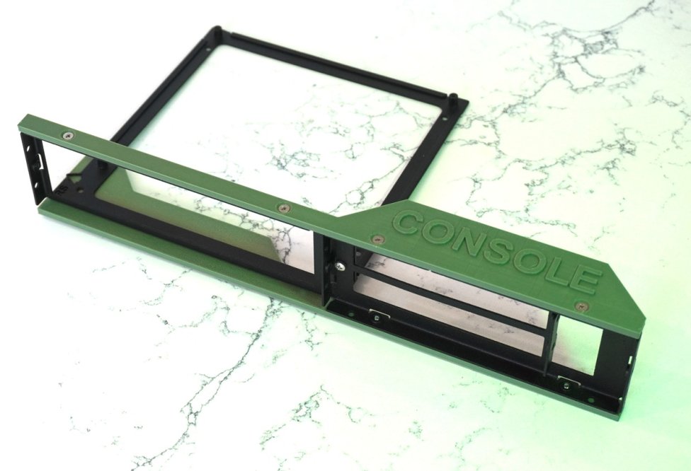
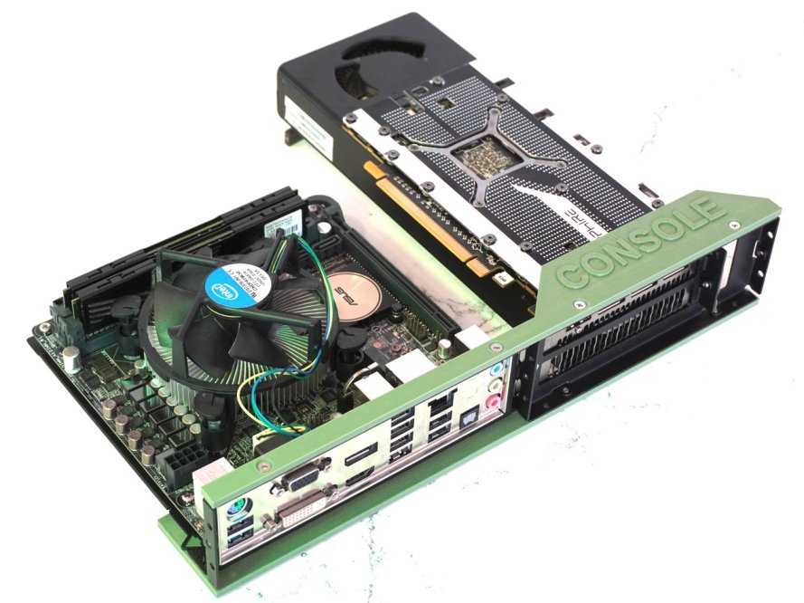
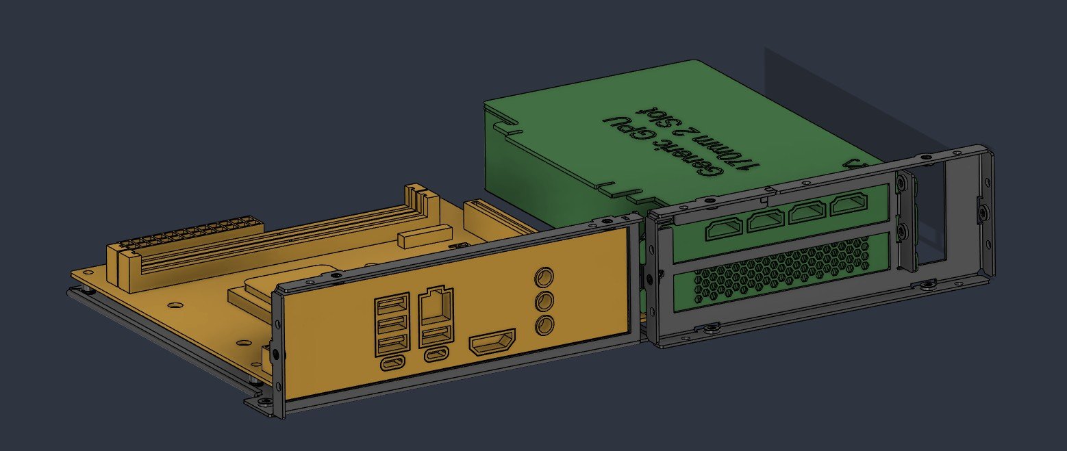
To that effect, I have here just a motherboard mounting bracket, and a gpu mounting bracket. They are sheet steel, with all the pcie-sig and atx mechanical specs baked in so you dont have to worry about it. There is an M3 mounting hole 28mm away from every corner, or an unthreaded hole 15mm away from every corner. This lets you bolt directly to the brackets, or bolt the brackets to something else. The best part: these can come together in either the traditional, sandwich, or console layout. So you can use these as a starting point to design your own case around them no matter the configuration you want.

Im currently waiting on quotes to get these prototyped, but would love any feedback from folks. Is this something you can see yourself trying out?
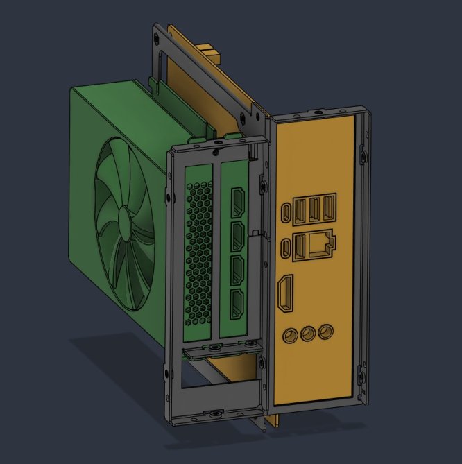
assembly_sandwich.jpg
assembly_console.jpg
assembly_traditional.jpg
assembly_exploded.jpg

Update 09/09/2026 the prototypes are here
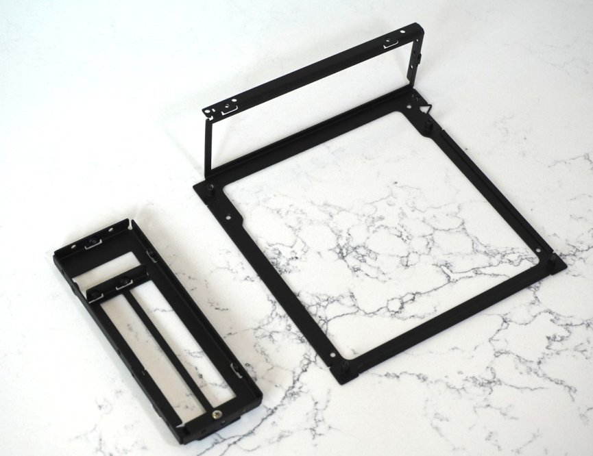
prototype_motherbaord_and_gpu.jpg

And, they even work as intended! All the tolerances work out, everything mounts as i hoped. Below spoilers with hardware installed and the 3 different orientations tested.
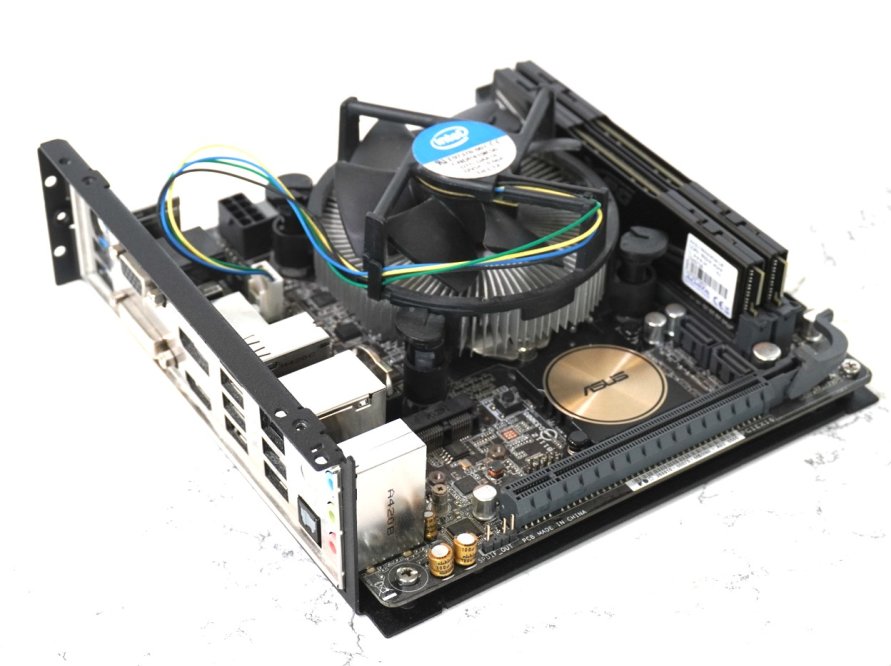
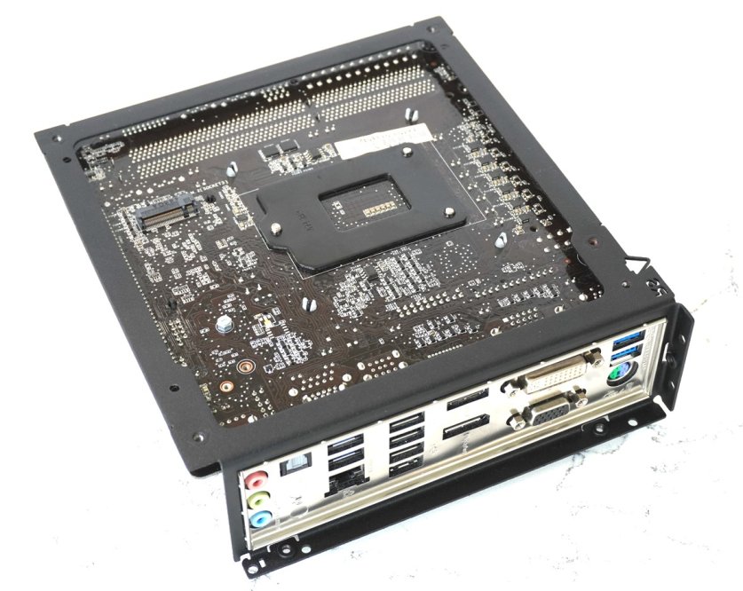
prototype_mobo_mount_top.jpgprototype_mobo_mount_bottom.jpg

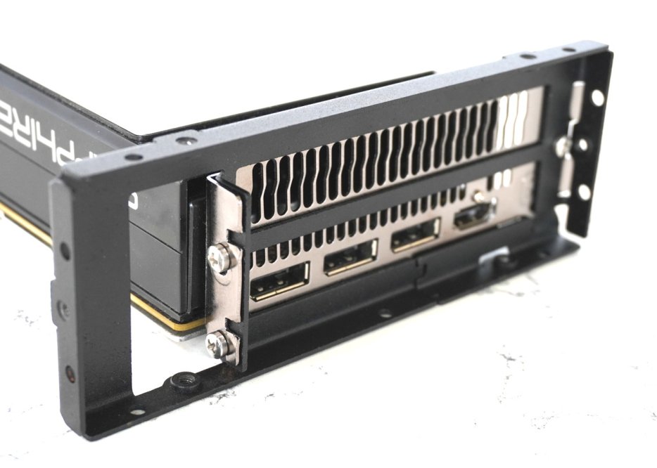
prototype_gpu_mount_top.jpg
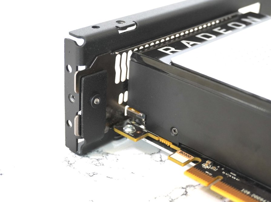
prototype_gpu_mount_bottom.jpg

The pinch plate on the bottom works very well to secure the GPU by pinching the pcie fingers. This worked out really well. The 2 M3 screws on the top however, where a gpu "usually"s crews in are difficult to install. There is not enough clearance to get a screw driver in there. Its workable for sure, just not convenient.
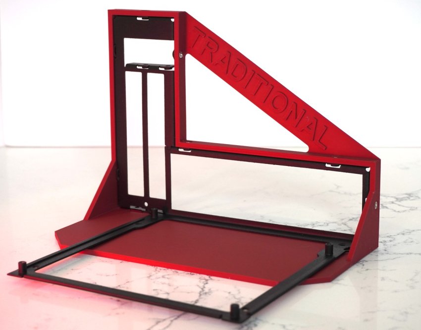
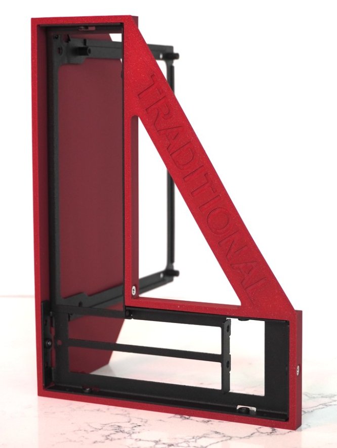
prototype_traditional_1.jpg
prototype_traditional_2.jpg
prototype_traditional_hardware.jpg

prototype_sandwich_1.jpg
prototype_sandwich_mobo_side.jpg
prototype_sandwich_gpu_side.jpg

prototype_console.jpg
prototype_console_hardware.jpg

Next steps are to otimize the design a little bit so its easier to work with.
My main 2 things id like to change after playing around with these are:
1) GPU mounting. Need to make installing the GPU easier. Probably going to optimize a flange away.
2) Nicer dimensions. In the traditional layout, there is no reason i cant make it also be nice whole mm dimensions, so il try to optimize that in.

There was also some feedback from reddit regarding a low profile gpu bracket. strongly considering that.
 
Last edited:

samsonbl4

Average Stuffer
Mar 11, 2026
64
33
37
I think these brackets definitely have practical value and would be well-suited for people who enjoy building custom PCs — for instance, inside household appliances or furniture. However, the current mounting method seems a bit inconvenient. I believe it would be better if the mounting direction to the outer casing aligned with the orientation of the I/O ports.
 

Shatrod

Airflow Optimizer
Gold Supporter
Dec 6, 2019
236
394
redshiftproject.com
I think these brackets definitely have practical value and would be well-suited for people who enjoy building custom PCs — for instance, inside household appliances or furniture. However, the current mounting method seems a bit inconvenient. I believe it would be better if the mounting direction to the outer casing aligned with the orientation of the I/O ports.
I've thought about this, it present a few challenges in its own right. Firstly sheet metal is only strong when it's folded. So the flanges around the perimeters are basically mandatory anyway crease the metal for strength. And equally importantly there is a keep out around the nuts. So if I put threaded nuts in plane with the IO the whole thing gets at the same time bigger and weaker. Or at the very least bigger.

I figured bigger is undesirable. But extending flanges in the direction of the IO shouldn't matter because you plug cables into there anyway. So you have to have room there regardless. Seemed like a logical place for the mounting hardpoints
 

samsonbl4

Average Stuffer
Mar 11, 2026
64
33
37
I completely agree that the bends are necessary for rigidity. However, I think it would be possible to add separate corners to the kit that attach to both the chassis and the outer case. You could also add holes to the motherboard frame for surface mounting, for example, when installing it inside a cabinet. A mounting template for marking the installation location would also be a great addition.
 

Shatrod

Airflow Optimizer
Gold Supporter
Dec 6, 2019
236
394
redshiftproject.com
I completely agree that the bends are necessary for rigidity. However, I think it would be possible to add separate corners to the kit that attach to both the chassis and the outer case. You could also add holes to the motherboard frame for surface mounting, for example, when installing it inside a cabinet. A mounting template for marking the installation location would also be a great addition.
Can you draw where you would put those holes? Almost the entire rear face of the motherboard bracket is the IO cutout
 

samsonbl4

Average Stuffer
Mar 11, 2026
64
33
37
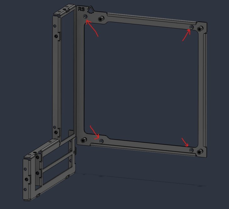
I think these holes will expand the installation options.

eDBNX.jpg
 

Shatrod

Airflow Optimizer
Gold Supporter
Dec 6, 2019
236
394
redshiftproject.com
I think these holes will expand the installation options.

eDBNX.jpg
Oh! Me and you are on the same page already then. Those motherboard standoffs are not blind. You can bolt down the motherboard and also bolt into the very same holes from the other side. So that installation option already exists!

I'm a little weary of adding extra holes or threads under the motherboard area because what if you poke the back of the motherboard with a screw and short it.
 

samsonbl4

Average Stuffer
Mar 11, 2026
64
33
37
It is good if there are threads on the other side. If you are concerned about the risk of a short circuit, you can countersink the holes for a flush-mount screw.
 

Shatrod

Airflow Optimizer
Gold Supporter
Dec 6, 2019
236
394
redshiftproject.com
It is good if there are threads on the other side. If you are concerned about the risk of a short circuit, you can countersink the holes for a flush-mount screw.
You're right. Even if the flush screw doesn't sit completely flush (not enough sheet metal thickness for that) its still lower to give more clearance. And the M3 screw head should clear the hem. Thanks for the suggestion, I have made the change:

new_holes.jpg
 
  • Like
Reactions: samsonbl4

samsonbl4

Average Stuffer
Mar 11, 2026
64
33
37
Looks good. What is the thickness of the sheet metal? I also think it would be good if for each of the layouts there were elements for rigidly fastening the frames together, so that the entire structure would be rigid.
 
Last edited:

Shatrod

Airflow Optimizer
Gold Supporter
Dec 6, 2019
236
394
redshiftproject.com
Looks good. What is the thickness of the sheet metal? I also think it would be good if for each of the layouts there were elements for rigidly fastening the frames together, so that the entire structure would be rigid.
It's 1.22mm cold rolled steel. (0.048" 18 gauge).

I initially had a version that bolts together as well but that made it notoriously difficult to support all 3 configurations while actually being rigid. I think all that rigidity will come from the substrate it's bolted to. Won't know until I prototype it to test though, looking for fabricators now
 

samsonbl4

Average Stuffer
Mar 11, 2026
64
33
37
I think you could try adding different small, simple-shaped fastening elements for each of the layouts. You'll end up with a universal main frame and a few non-universal small parts that won't significantly impact the final cost. And someone who wants to use your kit for their own DIY open frame, for example, will have the peace of mind that the base is sturdy.
 

Shatrod

Airflow Optimizer
Gold Supporter
Dec 6, 2019
236
394
redshiftproject.com
I think you could try adding different small, simple-shaped fastening elements for each of the layouts. You'll end up with a universal main frame and a few non-universal small parts that won't significantly impact the final cost. And someone who wants to use your kit for their own DIY open frame, for example, will have the peace of mind that the base is sturdy.
You'd be surprised how significantly part count impacts final cost. Unless the bracket is off the shelf it's an enormous cost driver in low volumes.

In fact that little pinch plate for the GPU that's part of the GPU bracket but is a separate piece is like 20% of the total cost. I'm still collecting quotes to see if I can make this economically viable, if not that piece is gona have to go
 

samsonbl4

Average Stuffer
Mar 11, 2026
64
33
37
What manufacturing technology do you want to use: laser cutting and bending on a universal bending press or stamping? The small part for the graphics card bracket looks simple, but I think this area is difficult to bend on a universal bending press.

eDT6N.jpg
 

Shatrod

Airflow Optimizer
Gold Supporter
Dec 6, 2019
236
394
redshiftproject.com
What manufacturing technology do you want to use: laser cutting and bending on a universal bending press or stamping? The small part for the graphics card bracket looks simple, but I think this area is difficult to bend on a universal bending press.

eDT6N.jpg
That's a joggle. I didn't think joggles are hard, I figured a hem is harder. I don't think I'm gona be doing enough volume to do stamping, I don't have that kind of cash. So laser and bending most likely. But I leave that up to the fab
 

samsonbl4

Average Stuffer
Mar 11, 2026
64
33
37
As I can tell from the image, there are two bends in different directions at this point, and the distance between them is very small. There won't be enough leverage for the second bend. However, I'm not a bending technologist and might be missing something.
 

Shatrod

Airflow Optimizer
Gold Supporter
Dec 6, 2019
236
394
redshiftproject.com
As I can tell from the image, there are two bends in different directions at this point, and the distance between them is very small. There won't be enough leverage for the second bend. However, I'm not a bending technologist and might be missing something.
None of the manufacturers have any cocerns about the joggle.
I got feedback, it is in fact the pem nuts and standoffs that are cost drivers for this. I can save a lot by omitting the pem nuts (i understand the standoffs are mandatory).


How important would you say is the ability to bolt to this part?
 

samsonbl4

Average Stuffer
Mar 11, 2026
64
33
37
I think any versatility will be useful in your DIY kit. But if eliminating the nuts will significantly reduce the cost, then it's better to do so. As I understand it, the nuts and standoffs in your design are welded in place?
 

Shatrod

Airflow Optimizer
Gold Supporter
Dec 6, 2019
236
394
redshiftproject.com
As I can tell from the image, there are two bends in different directions at this point, and the distance between them is very small. There won't be enough leverage for the second bend. However, I'm not a bending technologist and might be missing something.
No not welded. Press fit
 

samsonbl4

Average Stuffer
Mar 11, 2026
64
33
37
It's strange that this increases the price so much. I thought these press nuts were inexpensive and could be installed by hand with a hand tool.