Log [12V] B01T3 ...a 3L Brickless APU Build...

BaK

King of Cable Management
Original poster
Bronze Supporter
May 17, 2016
930
931


First things first, big thank to @Thehack for his 12V guide, his helpfulness, and all what he brings to the sff community!


So this build is a backup for my MiniCube rig. I need one as I am working more from home lately (Good excuse huh? ;))

Hardware parts:
- Open-Smart B01 case (200*200*75mm)
- MeanWell LSP-160-12T 160W 12V PSU (194*55*20mm)
- Pico-box Z2-ATX-200 200W 12v PDCB or RGEEK 250W 12 PDCB
- Gigabyte B450 I Aeorus Pro Wifi
- AMD Ryzen 5 3400G CPU
- Z39 CPU cooler with Noctua NF-A9x14 (bottom) and NF-A12x15 (top) ID_Cooling IS-60 EVO (92mm bottom fan only)
- Corsair Vengeance Pro RGB 2x 32GB DDR4 (no heatspreader/RGB)
- Samsung 970 EVO Plus 256GB M.2
- Samsung 970 EVO 1TB M.2
- Reset switch
? PSU ON/OFF switch
? Side USB3 or USB-C port


Last edited:

BaK

King of Cable Management
Original poster
Bronze Supporter
May 17, 2016
930
931
I actually bought two cases, a black and a silver one, and decided to mix them up. That makes it a little uncommon and that way I have a silver/black theme for both inside and outside the case. Except for the RGB memory kit maybe, which I bought because of its low price. I will see how I deal with it later as it actually add some restrictions because of the height of the modules.


Now here under the star of the build, the MeanWell LSP-160-12T PSU


This PSU is going on the front side of the case, where there is around 22-23mm clearance between the motherboard and the case.
Right now the power switch and the external USB3 ports are at that location (no pics sorry), they both have to be removed.
While I plan to replace the power button with a very short one, the USB3 ports will probably have to go.

It was supposed to be an easy fit on paper, PSU of 194mm into a case of 200mm.
But it turns out the case side panels are 3mm thick. So I have to actually fit a 194mm PSU into a 194mm case width.
Dremel needed!


Right now the PSU holds itself in place thanks to my cuttings. I will later add some thermal pads to attache the PSU to the front of the case.
Looking at the specs of the PSU, the latter should indeed be installed onto a plate to follow the thermal recommandations. Hopefully the case will act as a big heatsink!

On the last pic above, see the two squared holes at the front? The one on top is where the power button was protruding through, attached with some standoffs inside the case.
That's where I have to put another power switch that fit if I still want to use the original power button. There is only 1.5mm of height remaining once the PSU is in place. If needed I could still displace the PSU towards the back/motherboard and gain 1 or maybe 2 mm.
I am waiting for some power switch to arrive in the mail before deciding if it is doable or if I have to change my plan for a power button at the back of the case, and a fake one on the front side...


While playing with the Dremel, I also enlarged the hole for the power connector at the back of the case.
This hole was initially made for a connector to which an external brick can be connected, but I am installing this one instead:
a CNLink M12 3pin connector


[to be continued...]
 

robbee

King of Cable Management
n3rdware
Bronze Supporter
Sep 24, 2016
855
1,335
The fit of that PSU is so pleasing! Looking forward to see more of this build.
 

Valantar

Shrink Ray Wielder
Jan 20, 2018
2,201
2,225
Looking good! Definitely following this build. I really like that MeanWell too, looks like a thinner version of their UHP series. How are you connecting your power wiring, given the short clearances? Are you just clamping the wiring directly in the screw terminal, or are you squeezing in a 90° bent terminated wire in there somehow?
 

BaK

King of Cable Management
Original poster
Bronze Supporter
May 17, 2016
930
931
Very nice! 12v lives!
Thanks!
If all goes according to ma plan yes! But a 160W should be enough for that modest build.

The fit of that PSU is so pleasing! Looking forward to see more of this build.
Yeah, happy how my cutouts went and how the PSU aligns with the case! :cool:

I'm jealous with that Meanwell.. Anw, in case you need some reference:


Edit: you may want to file the sharp corners.
Thanks for the link, don't know how I missed you review!
I will look at it closely, just browse through it now and found the pic I forgot to take where we see the external USB and power button fixations:

No room for them there anymore!

I will be careful with the sharp edges you mentioned, but they didn't bother me so far, no bleeding fingers yet!
And oh, funny thing is that I first planned to use the MSI B450I motherboard but switched to the Gigabyte because of its USB3 Gen2 ports. I have a SanDisk Extreme Pro external SSD to test them with!
 

BaK

King of Cable Management
Original poster
Bronze Supporter
May 17, 2016
930
931
Looking good! Definitely following this build. I really like that MeanWell too, looks like a thinner version of their UHP series.
Thanks!
The UHP-200-12 was actually what I wanted to use first, but once having the case in my hands it was obvious there was no room for the 26mm of height of this PSU.
Kind of lucky they also make the LSP serie!

How are you connecting your power wiring, given the short clearances? Are you just clamping the wiring directly in the screw terminal, or are you squeezing in a 90° bent terminated wire in there somehow?
Yes, the idea is indeed to bend the terminal rings at 90°. Something like that:


but with such a, more discreet, terminal:

Just hope that bending it will not break it and that there will be room enough for a couple of them on a single screw terminal.
 
  • Like
Reactions: Valantar

BaK

King of Cable Management
Original poster
Bronze Supporter
May 17, 2016
930
931
Just some shots of the ID-Cooling IS-60 EVO CPU cooler.
I will use it without the 120mm top fan it is sold with, only keeping the smaller 92mm fan at the bottom.


I like the mirror effect but still wonder, as it comes from nickel plating, if that added layer really helps in heat dissipation.


Unlike what has been said in the IS-47K thread
Yeah, I have the IS-47K too and the stock ID-Cooling fan doesnt allow to be placed as intake as the fan blades will hit the fins/mounting fan frame. A9x14 doesn't have this issues as the fan blades are flatter and has the rubber pads too. You need some kind of spacer or pad to make the ID-Cooling fan work as intake.
this "ID-92 15M 12S" stock bottom fan came installed as intake and works flawlessly in that orientation.
I notice four rubber ring washer between the heatsink and the fan though, ID-Cooling probably adds them in this version of their cooler.


While I should have tested the cooler without it first, for comparison sake, I ended up installing it directly with the Noctua l9al9i mounting kit backplate.
I will see later if swapping the fan for a Noctua is worth it, but that's almost sure I am going to add a fan duct to avoid hot air recycling.
 
  • Like
Reactions: Valantar

aquelito

King of Cable Management
Piccolo PC
Feb 16, 2016
952
1,122
Thanks!
The UHP-200-12 was actually what I wanted to use first, but once having the case in my hands it was obvious there was no room for the 26mm of height of this PSU.
Kind of lucky they also make the LSP serie!


Yes, the idea is indeed to bend the terminal rings at 90°. Something like that:


but with such a, more discreet, terminal:

Just hope that bending it will not break it and that there will be room enough for a couple of them on a single screw terminal.
I think I have some cable harnesses with bend ring terminals left if you want to test stuff without shelling too much money at Mouser :)
 
  • Like
Reactions: BaK

BaK

King of Cable Management
Original poster
Bronze Supporter
May 17, 2016
930
931
I think I have some cable harnesses with bend ring terminals left if you want to test stuff without shelling too much money at Mouser :)
Thanks a lot for the proposal! I'll pm you about it.
 

BaK

King of Cable Management
Original poster
Bronze Supporter
May 17, 2016
930
931


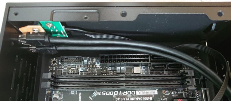
As you must have noticed, the room left for the PDCB is very tight!
Almost nothing on the PSU side and a few mm on the memory side. Furthermore with the RAM I have chosen, which is as high as the PDCB.


Here without the PSU in place, you can see how the white connector on the PDCB would either be conflicting, here with the PSU, or with the RAM on the other side.

That's why this connector will have to be removed. The latch on the 24Pin as well as it protrudes way to much into the PSU area.
I will also probably have to unsolder the 12V input cables of the PDCB and put them on the memory side.


Now to the real stuff!
For this test, the LSP160 is coupled with the Z2-ATX-200 PDCB.
But without the white connector on the PDCB, the CPU 4pin EPS has to be attached straight to the LSP160.


From the 12v Guide thread, @Thehack mentionned that this could be a problem on some motherboards. Fingers crossed this Gigabyte one will accept it!
And...


It's alive, so cool!!! \o/

I did a test on an old mobo first, but was still a bit nervous!
It's usually nice to see the BIOS menu on a first test, but it is even nicer this time as nothing caught on fire! :)
 

Valantar

Shrink Ray Wielder
Jan 20, 2018
2,201
2,225


As you must have noticed, the room left for the PDCB is very tight!
Almost nothing on the PSU side and a few mm on the memory side. Furthermore with the RAM I have chosen, which is as high as the PDCB.


Here without the PSU in place, you can see how the white connector on the PDCB would either be conflicting, here with the PSU, or with the RAM on the other side.

That's why this connector will have to be removed. The latch on the 24Pin as well as it protrudes way to much into the PSU area.
I will also probably have to unsolder the 12V input cables of the PDCB and put them on the memory side.


Now to the real stuff!
For this test, the LSP160 is coupled with the Z2-ATX-200 PDCB.
But without the white connector on the PDCB, the CPU 4pin EPS has to be attached straight to the LSP160.


From the 12v Guide thread, @Thehack mentionned that this could be a problem on some motherboards. Fingers crossed this Gigabyte one will accept it!
And...


It's alive, so cool!!! \o/

I did a test on an old mobo first, but was still a bit nervous!
It's usually nice to see the BIOS menu on a first test, but it is even nicer this time as nothing caught on fire! :)
Nice! But doesn't that mean that the CPU VRM is getting 12V supplied to it even when the system is off? That doesn't sound ideal, even if I would hope the entire VRM is shut down at that point and no voltage is passed to the CPU. As such, wouldn't soldering the 4-pin onto the pads for the white connector be a better solution long-term?
 
  • Like
Reactions: BaK

REVOCCASES

Shrink Ray Wielder
REVOCCASES
Silver Supporter
Apr 2, 2020
2,057
3,331
www.revoccases.com
Nice! But doesn't that mean that the CPU VRM is getting 12V supplied to it even when the system is off? That doesn't sound ideal, even if I would hope the entire VRM is shut down at that point and no voltage is passed to the CPU. As such, wouldn't soldering the 4-pin onto the pads for the white connector be a better solution long-term?

Yes, the VRMs will get 12V all the time but they seem not to pass on any voltage to the CPU if the PC is switched off. They are acting similar like a load switch. We've also tested this in the 12v thread somewhere. Not yet sure if this has any effect on the VRMs long term though.

If you are more comfortable switching off the power for the CPU completely, this load switch board could be a solution:


I made this together with G-unique especially for such a scenario where you want to switch off a GPU or CPU when connecting directly to a 12v source.
 
  • Like
Reactions: BaK and Valantar

BaK

King of Cable Management
Original poster
Bronze Supporter
May 17, 2016
930
931
Nice! But doesn't that mean that the CPU VRM is getting 12V supplied to it even when the system is off? That doesn't sound ideal, even if I would hope the entire VRM is shut down at that point and no voltage is passed to the CPU. As such, wouldn't soldering the 4-pin onto the pads for the white connector be a better solution long-term?
Soldering is still an option yes, but I followed what did @Thehack with his build in the 12V thread so I am confident it is ok like that.

He actually also answered a question about the best of these two options, 'A' straight from the PSU and 'B' through the PDCB: https://smallformfactor.net/forum/threads/a-guide-to-12v-psu.1270/post-123938
1. Set up A is the best electrically. But some motherboards react strangely to having 12V rail always on even when the PC is off. B is most reliable way of ensuring it works properly.

Thanks @REVOCCASES for adding these technical pieces of information!
 

Thehack

Spatial Philosopher
Creator
Mar 6, 2016
2,800
3,650
J-hackcompany.com
Mind to explain?
Let's say you use 12V from a fan header to control the load switch. How does the motherboard get that 12V? It gets from the same source that the load switch is triggering.

If you turn your computer off, the 12V doesn't turn off because the motherboard controls the 12V, the 12V turns off because the PSU turns off. In this case, it is "latched" on. If the fan header uses the same source as the load switch, you can't use it to trigger itself.

Think about it, if you're an EE, what is the simplest way to do a fan header? Tie the fan header to the 12V rail, which is only on when the computer is actually on.

Even if you use 5V to control it, it may not be effective. Some 5V rails are "passive" rail, in that they just regulate 5V whenever there is 12V.

Now, it really just depends on the motherboard. Some fancy motherboards may have the fan header attached to the power controller and a separate VRM.
 
  • Like
Reactions: Valantar

REVOCCASES

Shrink Ray Wielder
REVOCCASES
Silver Supporter
Apr 2, 2020
2,057
3,331
www.revoccases.com
Let's say you use 12V from a fan header to control the load switch. How does the motherboard get that 12V? It gets from the same source that the load switch is triggering.

If you turn your computer off, the 12V doesn't turn off because the motherboard controls the 12V, the 12V turns off because the PSU turns off. In this case, it is "latched" on. If the fan header uses the same source as the load switch, you can't use it to trigger itself.

Think about it, if you're an EE, what is the simplest way to do a fan header? Tie the fan header to the 12V rail, which is only on when the computer is actually on.

Even if you use 5V to control it, it may not be effective. Some 5V rails are "passive" rail, in that they just regulate 5V whenever there is 12V.

Now, it really just depends on the motherboard. Some fancy motherboards may have the fan header attached to the power controller and a separate VRM.

Well, I don't know about any other load switch module for such an application, so I guess you are referring to the GxR-DIY.

I am happy to explain how it works: First of all the GxR-DIY is not a stand alone component. Of course you still need a DC ATX PLUGIN or similar PSU. Now let's say your PLUGIN only gives you 160W but you need more power. Either for CPU or GPU, doesn't matter. Then you can hook the GxR-DIY between a 12VDC PSU and the component you want to power. In BaKs build for example it would sit between the Meanwell and the CPU 4PIN. The +2V to 20V "signal" to turn the GxR-DIY on and off can come from: fan header, SATA Power header, USB header, etc... It does not really matter from which pin/header the + signal comes from because the PLUGIN will turn voltages on these headers on the motherboard on and off when you switch your PC on and off. If it would not, and lets say there would still be 12V on your fan headers after you have switched off your PC, the fans would keep spinning, right? We tested it with about ten different motherboards and several PLUGINs and it always worked. No magic involved. It's more or less like a simple fancy relay.

If you have a NUC, DeskMini or other mini PC with DC in and want to add a GPU using the GxR Load Switch it's even easier because then you do not need a PLUGIN.

I would call that a pretty universal solution to solve the "always on" issue while you do not have to choose an AC-DC PSU with PSON function.

Anyways, this is @BaK 's build thread and he already has found a solution to power his build, so I propose to move the load switch discussion to the GxR-DIY thread if there should still be questions if/how this works.
 
Last edited:

Thehack

Spatial Philosopher
Creator
Mar 6, 2016
2,800
3,650
J-hackcompany.com
Well, I don't know about any other load switch module for such an application, so I guess you are referring to the GxR-DIY.

I am happy to explain how it works: First of all the GxR-DIY is not a stand alone component. Of course you still need a DC ATX PLUGIN or similar PSU. Now let's say your PLUGIN only gives you 160W but you need more power. Either for CPU or GPU, doesn't matter. Then you can hook the GxR-DIY between a 12VDC PSU (you could even use two separate PSUs for PLUGIN and GxR-DIY) and the component you want to power. In BaKs build for example it would sit between the Meanwell and the CPU 4PIN. The +2V to 20V "signal" to turn the GxR-DIY on and off can come from: fan header, SATA header, USB header, etc... It does not really matter from which pin/header the + signal comes from because the PLUGIN will turn voltages on these headers on the motherboard on and off when you switch your PC on and off. If it would not, and lets say there would still be 12V on your fan headers after you have switched off your PC, the fans would keep spinning, right? We tested it with about ten different motherboards and several PLUGINs and it always worked. No magic involved. It's more or less like a simple relay.

If you have a NUC, DeskMini or other mini PC with DC in and want to add a GPU using the GxR Load Switch it's even easier because then you do not need a PLUGIN.

I would call that a pretty universal solution to solve the "always on" issue while you do not have to choose an AC-DC PSU with PSON function.

Anyways, this is @BaK 's build thread and he already has found a solution to power his build, so I propose to move the load switch discussion to the GxR-DIY thread if there should still be questions if/how this works.

I already explained, it matters. You cannot just use SATA header, fan header, in all situations because they may be directly tied to the 12V rail.

You can trigger it if you use logic triggering from your plugin, but using a fan header is not logic, it is a power rail. You can't use power to trigger power, because then it'll feedback loop itself and latch in the 'on' state.

I don't want to argue, but if you don't understand it's okay. Just don't be surprised that it may not work in all situations.