
Earlier this year, we previewed ASRock’s “Little Monster”, their X299E-ITX/ac motherboard, with a featureset longer than some motherboard’s manuals, and a board density to suit. The X299E-ITX/ac was shown with not one, but two daughterboards! The board was launched at Computex 2017, and we just so happened to be there, thanks to our community.
After looking over the spec list, having a hands-on with a display unit, and passing on the news to the community, we waited.. and waited. Just like a kid waiting for Christmas, we waited. Well, the time has come, and here it is!
Table of Contents
The Moniker
So, where did the “Little Monster” name come from? During ASRock’s Computex 2017 press conference, the board was listed alongside the rest of ASRock’s X299 range, each of which carried a use case, or suggested market. However, the X299E-ITX/ac was listed a little differently. Instead of a “SFF”, “Portable workstation” or similar moniker, the board was listed as “The Little Monster”, hinting at the board’s devilishly complex design.

The Specs
| Model | ASRock X299E-ITX/ac |
| Form Factor | M-ITX (17x17cm) |
| CPU Socket | LGA2066 |
| CPU Support | Skylake-X 6 cores and above with 28 or 44 PCIe lanes |
| Memory Support | Up to 64GB (16GB per module), 4x DDR4 SODIMMs, DDR4 4000+(OC)/ 3866(OC)/ 3800(OC)/ 3733(OC)/ 3600(OC)/ 3200(OC)/ 2933(OC)/ 2800(OC)/ 2666/ 2400/ 2133 |
| Memory Channels | Up to quad channel |
| Onboard Video | None |
| Expansion Slots | 1 x PCI Express 3.0 x16 Slot (PCIE1: x16 mode) |
| Other Slots | 1 x Vertical M.2 Socket (Key E) with the bundled Wi-Fi 802.11 ac module (on the rear I/O) |
| Storage | 6 x SATA3 6.0Gb/s Connectors, support RAID, NCQ, AHCI and Hot Plug, 1 x Ultra M.2 Socket (M2_1), supports M Key type 2230/2242/2260/2280 M.2 SATA3 6.0Gb/s module and M.2 PCI Express module up to Gen3 x4 (32Gb/s)** 2 x Ultra M.2 Sockets (M2_2 and M2_3), support M Key type 2280 M.2 PCI Express module up to Gen3 x4 (32Gb/s)** ** Supports Intel Optane Technology (M2_1) ** Supports NVMe SSD as boot disks ** Supports Virtual RAID On CPU (M2_2 and M2_3) |
| RAID | 0/1/5/10 |
| Onboard Audio | Realtek ALC1220, 7.1 Channels |
| Wired LAN | Intel I219-V Gigabit x1, Intel I211-AT Gigabit x1. |
| WiFi | Intel 802.11 ac 8265 Dual Band |
| Bluetooth | Bluetooth 4.2/3.0 + high speed class II |
| Rear IO | 2 x RJ45 for Gigabit Ethernet 1 x USB 3.1 Gen2 Type-A Port (10Gb/s) (ASMedia ASM3142) (Supports ESD Protection) 1 x USB 3.1 Gen2 Type-C Port (10Gb/s) (ASMedia ASM3142) (Supports ESD Protection) 4 x USB 3.1 Gen1 Ports (Supports ESD Protection) 2 x WiFi antenna 1 x S/PDIF 5 x 3.5mm Audio – Rear Speaker / Central / Bass / Line in / Front Speaker / Microphone |
| Internal IO | 1 x USB 2.0 Header 1 x USB 3.1 Gen1 Header from ASMedia ASM1074 Hub 1 x Virtual RAID On CPU Header (VROC) 1 x TPM Header 1 x Power LED and Speaker Header 1 x RGB LED Header * Supports in total up to 12V/3A, 36W LED Strip 1 x CPU Fan Connector (4-pin) * The CPU Fan Connector supports the CPU fan of maximum 1A (12W) fan power. 1 x CPU Optional/Water Pump Fan Connector (4-pin) (Smart Fan Speed Control) * The CPU Optional/Water Pump Fan supports the water cooler fan of maximum 1.5A (18W) fan power. 1 x Chassis Fan Connector (4-pin) (Smart Fan Speed Control) * CPU_OPT/W_PUMP and CHA_FAN1 can auto detect if 3-pin or 4-pin fan is in use. 1 x Front Panel Audio Connector (15µ Gold Audio Connector) 1 x Rear Button Switch (A: Clear CMOS Button; B: Power Button) |
| Power Connectors | 1 x 24 Pin ATX Connectors, 1 x 8 Pin 12v Power Connecotr |
| Features | Unique Feature: ASRock USB 3.1 Gen2 – ASRock USB 3.1 Gen2 Type-A Port (10Gb/s) – ASRock USB 3.1 Gen2 Type-C Port (10Gb/s) ASRock Super Alloy – Premium 60A Power Choke – Dr. MOS – Nichicon 12K Black Caps (100% Japan made high quality conductive polymer capacitors) – Matte Black PCB – High Density Glass Fabric PCB Intel 802.11 ac Wi-Fi 8265 (AC Wave 2 + BLE BT4.2) ASRock Steel Slots ASRock Ultra M.2 (PCIe Gen3 x4 & SATA3) ASRock Full Spike Protection (for all USB, Audio, LAN Ports) ASRock Live Update & APP ShopBIOS Feature: – 128MB AMI UEFI Legal BIOS with multilingual GUI support – ACPI 6.1 Compliant wake up events – SMBIOS 3.0 Support – CPU, DRAM, PCH 1.0V, VCCIO, VCCSA,Voltage Multi-adjustmentSupport CD: – Drivers, Utilities, AntiVirus Software (Trial Version), Google Chrome Browser and ToolbarSoftware and UEFI: – ASRock A-Tuning – ASRock RGB LED – ASRock XFast LAN * These utilities can be downloaded from ASRock Live Update & APP Shop. UEFI – ASRock EZ Mode – ASRock Full HD UEFI – ASRock My Favorites in UEFI – ASRock Instant Flash – ASRock Internet Flash – ASRock Crashless BIOS – ASRock UEFI System Browser – ASRock UEFI Tech Service – ASRock Easy RAID InstallerHardware Monitor: – Temperature Sensing: CPU, CPU Optional/Water Pump, Chassis Fans – Fan Tachometer: CPU, CPU Optional/Water Pump, Chassis Fans – Quiet Fan (Auto adjust chassis fan speed by CPU temperature): CPU, CPU Optional/Water Pump, Chassis Fans – Fan Multi-Speed Control: CPU, CPU Optional/Water Pump, Chassis Fans – Voltage monitoring: +12V, +5V, +3.3V, CPU Vcore, DRAM, PCH 1.0V, VCCIO, VCCSAOS: – Microsoft Windows 10 64-bitCertifications: – FCC, CE, WHQL – ErP/EuP ready (ErP/EuP ready power supply is required) |
| Package Contents | Accessories – Quick Installation Guide, Support CD, I/O Shield – 2 x SATA Data Cables – 1 x ASRock Wi-Fi 2.4/5 GHz Antenna – 3 x Screws for Ultra M.2 Sockets |
| RRP | Around US$399.99 |
The Unboxing

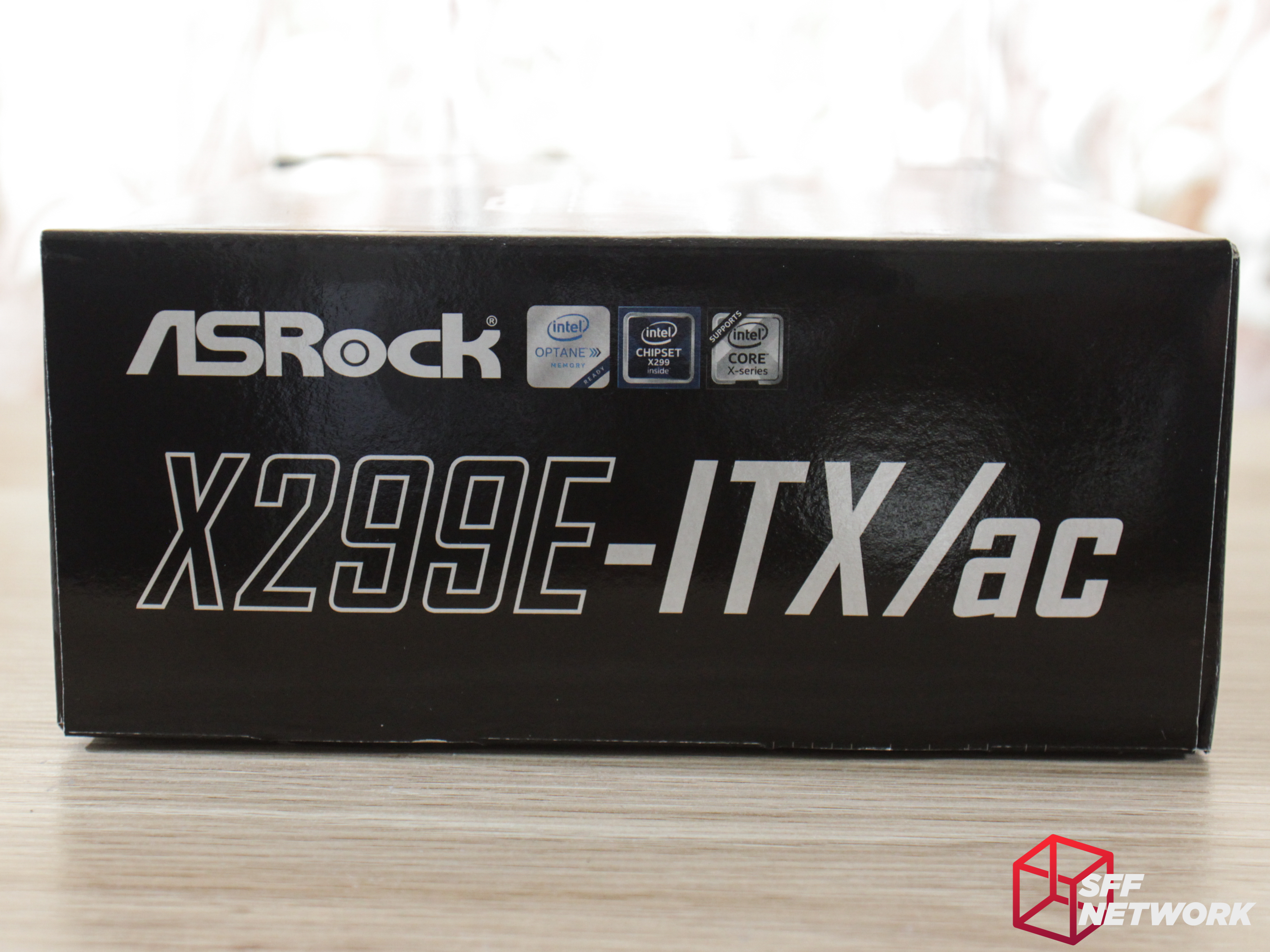
The box design is subtle, understated. No hint as to the powerhouse that hides inside this simple cardboard box. Can you tell I’m excited?

The back of the box is a little more vocal about what’s inside. What I note here is no “GAMER!”, workstation, or whatever branding. ASRock has decided to let the product speak for itself.
Even the ends of the boxes are clean and subtle.
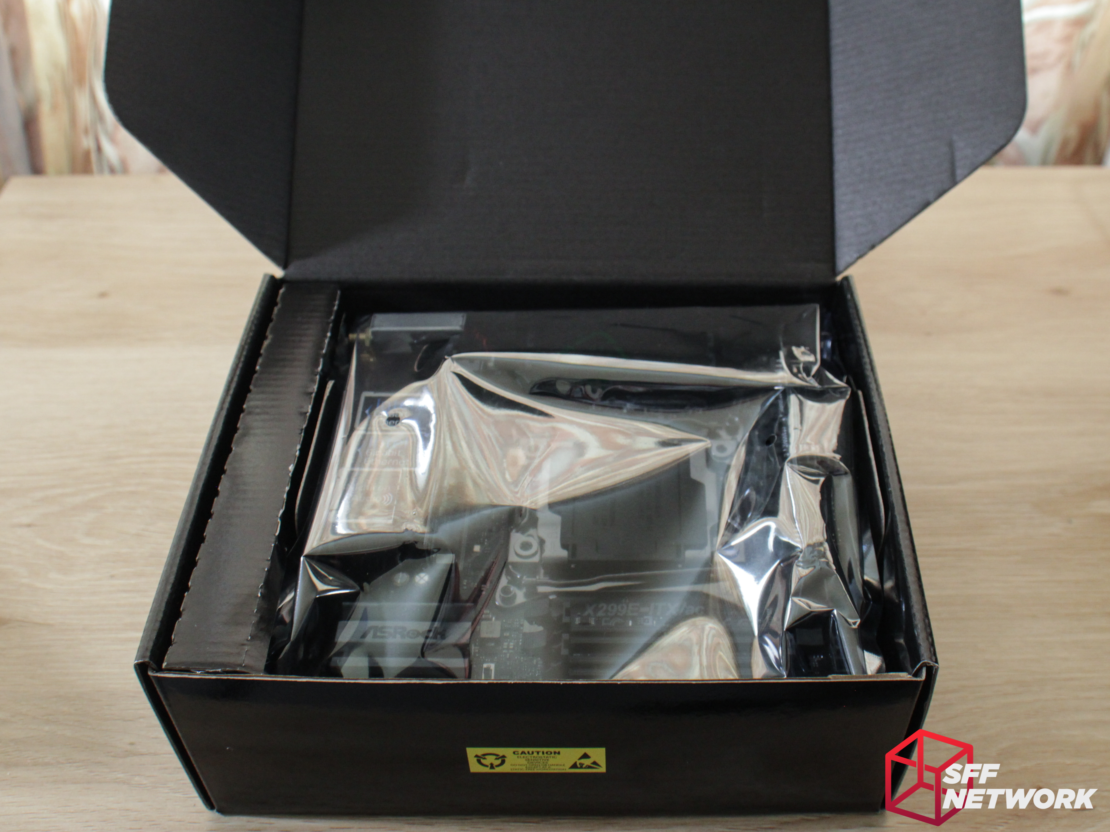
Opening the box, we are greeted with the board, nestled in safely with just an antistatic bag protecting it. Two layers of corrugated cardboard is what’s protecting the “Little Monster” from the not so nice monsters that are on the path from factory to you.
The Accessories and Software
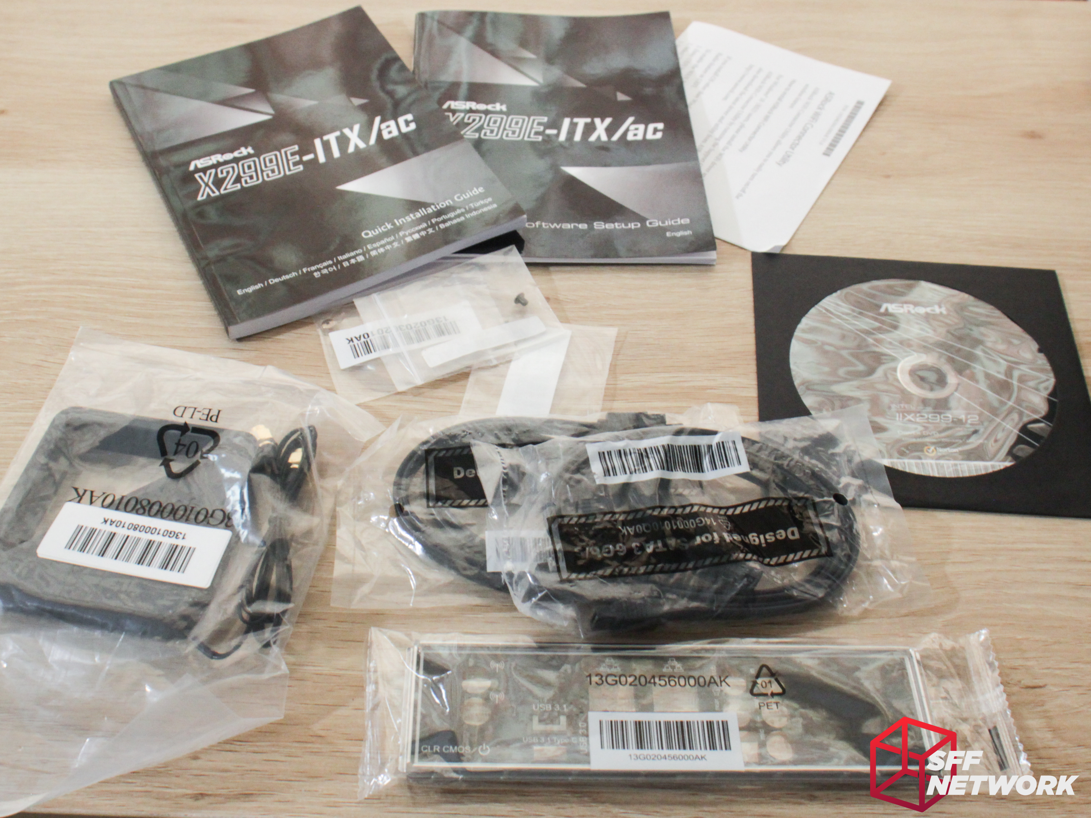
Included with the ASRock X299E-ITX/ac are a small selection of accessories, a little less than I’d expect for the asking price for the board. However, the board itself is pretty well featured so I suppose that this is a moderately acceptable trade-off. We see two pairs of SATA cables, a dual band WiFi antenna, a user manual, 3 x M.2 mounting screws, a case sticker, and lastly, the all-important IO shield.
The ASRock X299E-ITX/ac
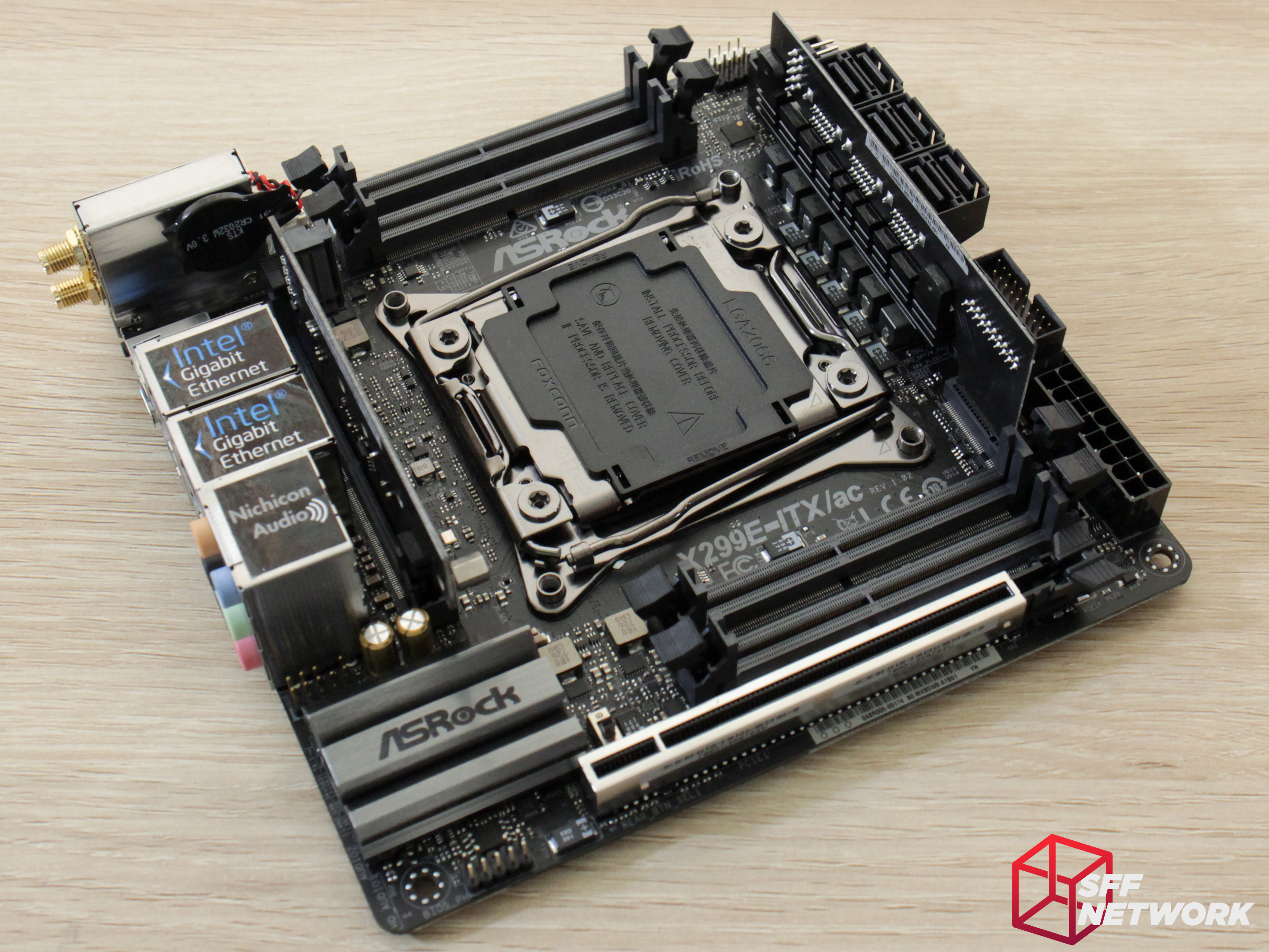
And here we have it, the production model of the ASRock X299E-ITX/ac. At first glance, we can see not a huge amount has changed from the initial mockups, but a few design tweaks have taken place, which we will analyse in full as we inspect the motherboard!
You can really see how tight the board layout is. There isn’t a square millimetre to spare, no gimmicks, flashiness or other gubbins that would take up otherwise useful room.
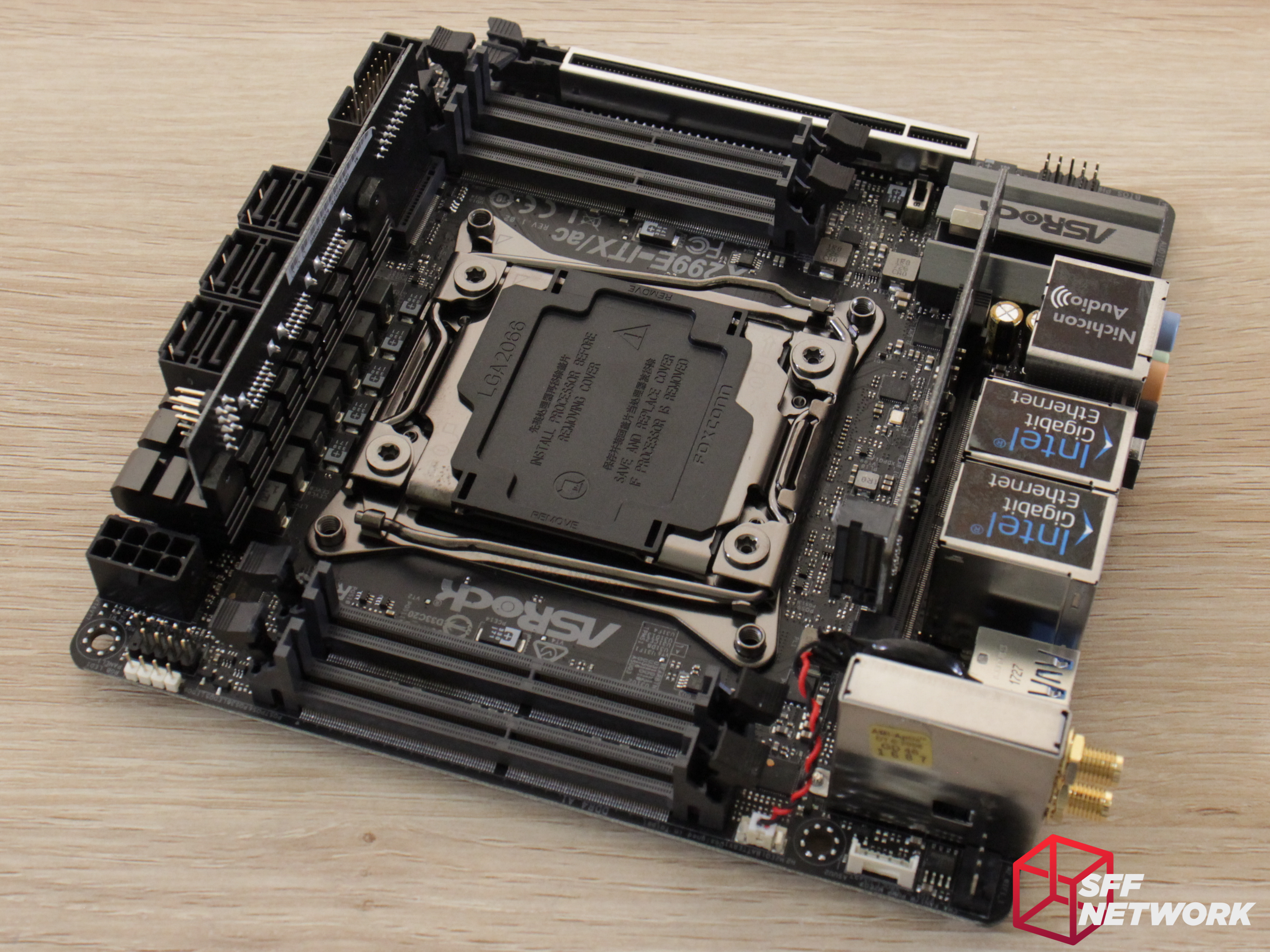
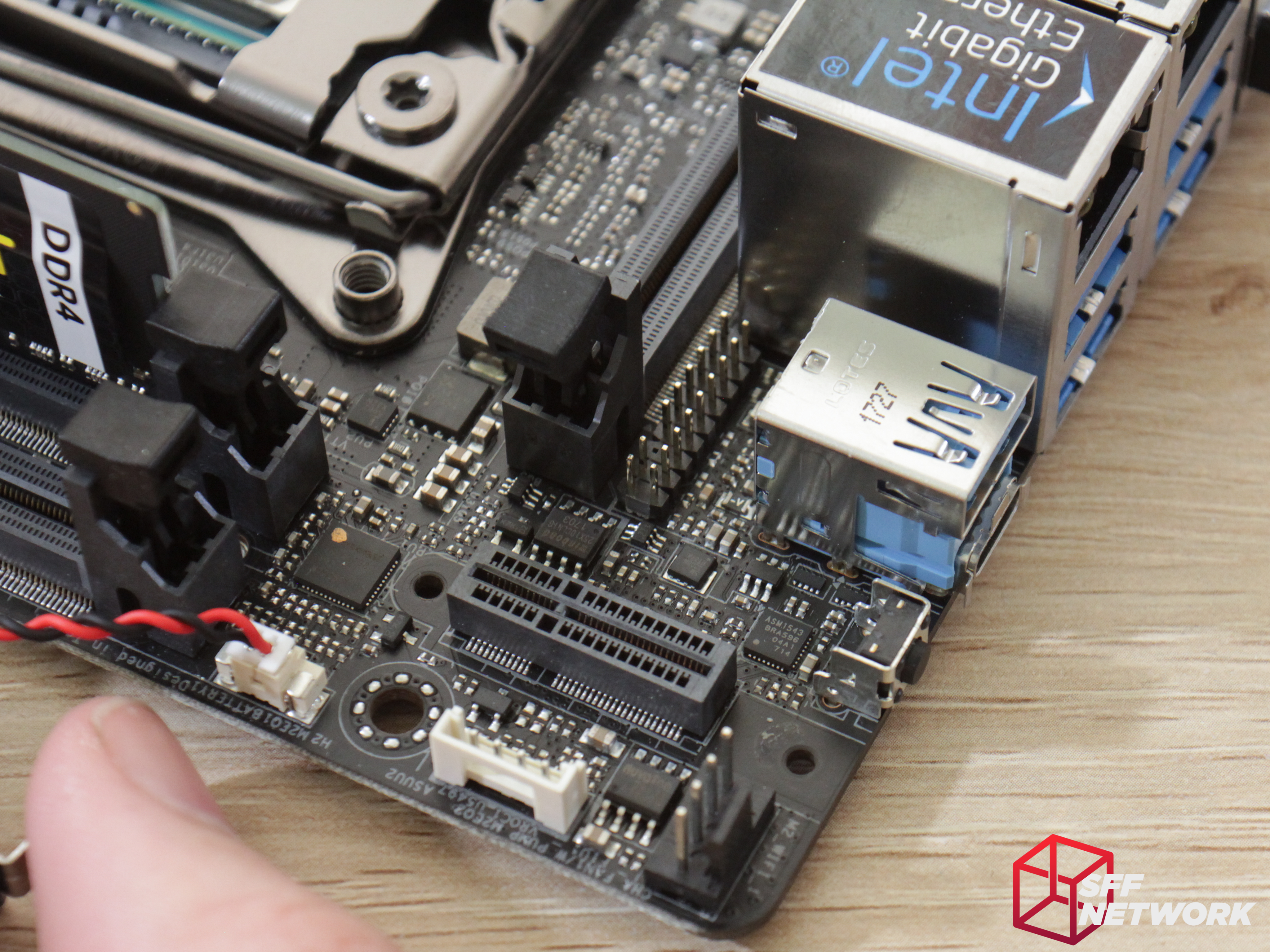
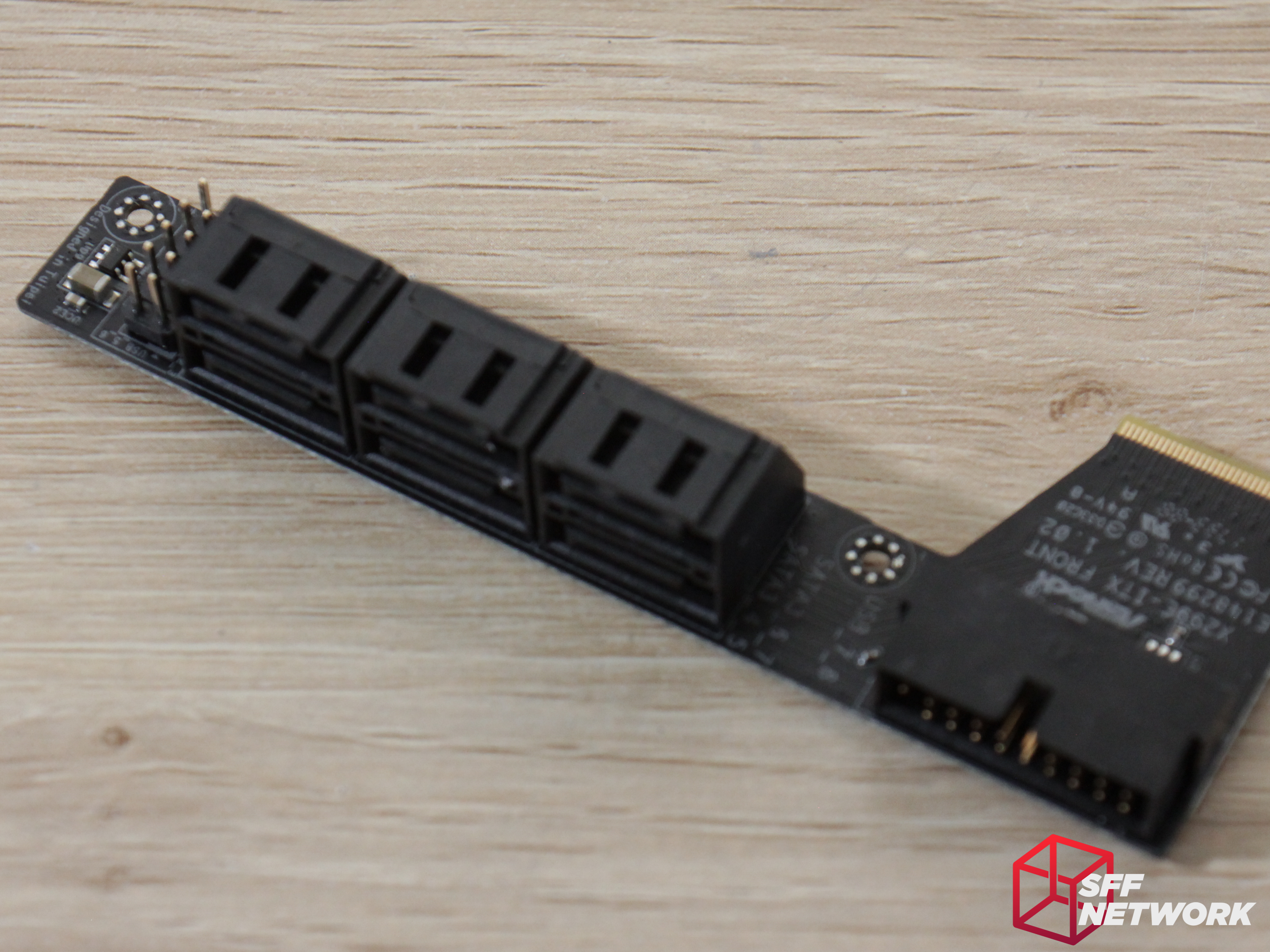
From the front of the board, we can see even more crammed in ports, including the six SATA 6Gb/s ports, the front panel USB3.0 and USB2.0 headers, and more. The USB2.0 header here is an important change – according to our resident pixel analyser James, the board mockup placed the front panel header here, meaning that you had to have this daughterboard installed to power on the system! Since that time, it seems that ASRock has looked over this daughterboard again and decided that wasn’t the best plan of action. Indeed, with three M.2 slots on board minimising the need for the SATA ports, you could remove this front daughterboard entirely to aid in airflow.
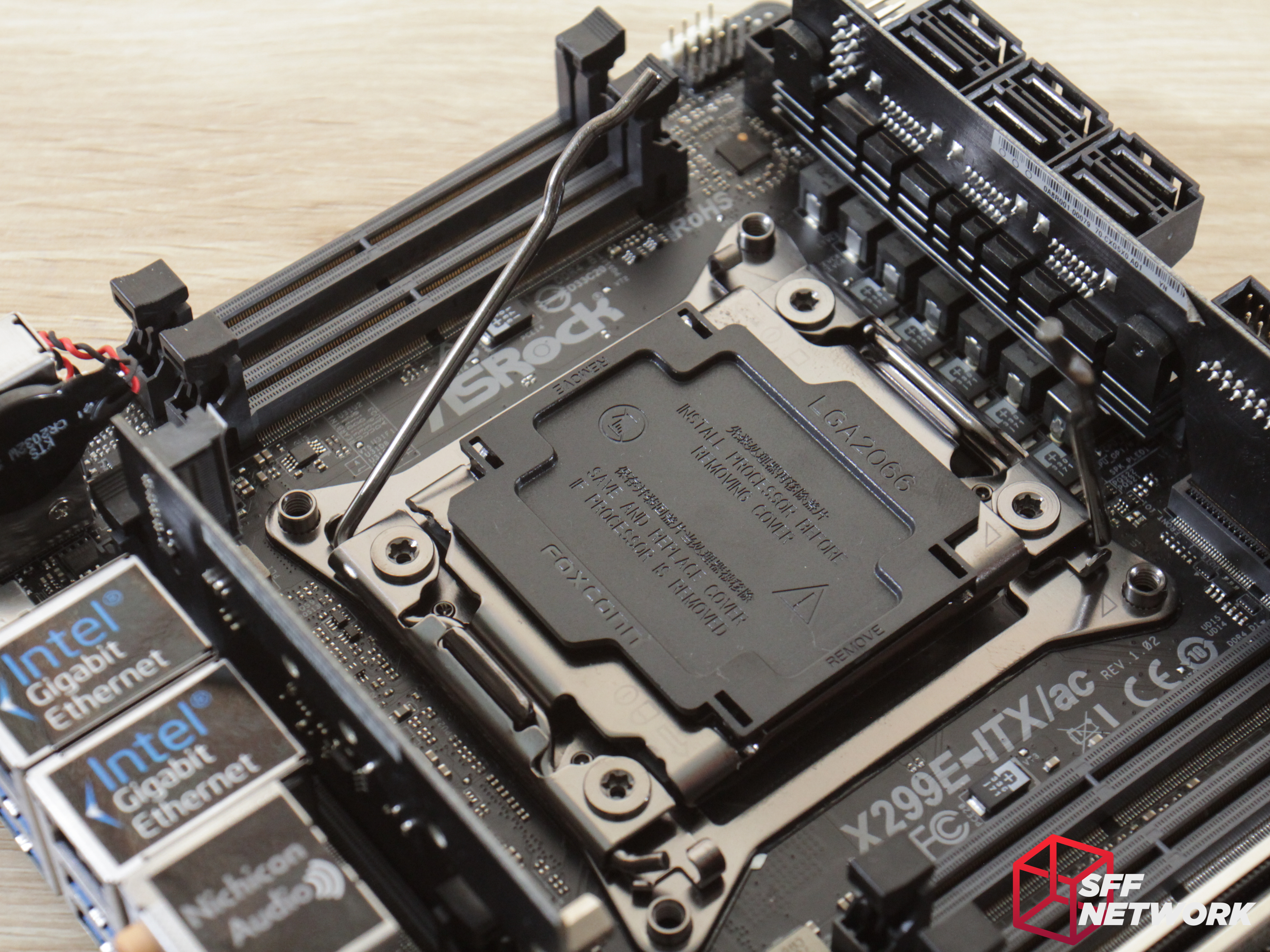
How they managed this, I don’t know. This is a full square ILM Intel LGA2066 socket residing front and centre in the X299E-ITX/ac. Remembering on the previous generation crazy motherboard from ASRock, the X99E-ITX/ac, ASRock was forced to use the narrow ILM due to space considerations. This led to a host of cooler compatibility issues, which made it a more challenging build than it could have been (not that SFF isn’t a fantastic challenge in and of itself).
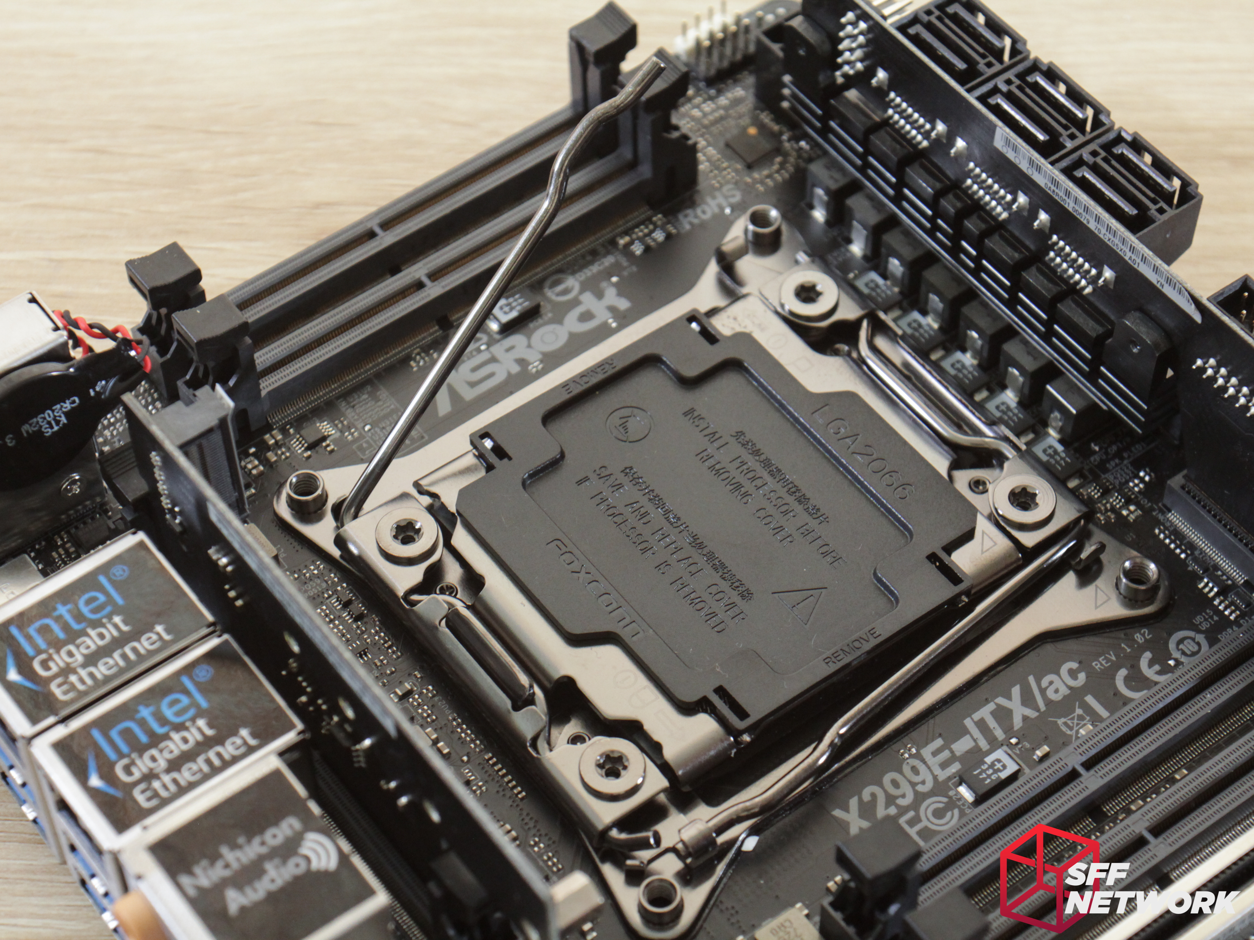
Lets get that Intel Skylake-X CPU installed shall we? The LGA2066 socket is different from the consumer segment LGA sockets from Intel, with two steel arms holding down the retention plate.
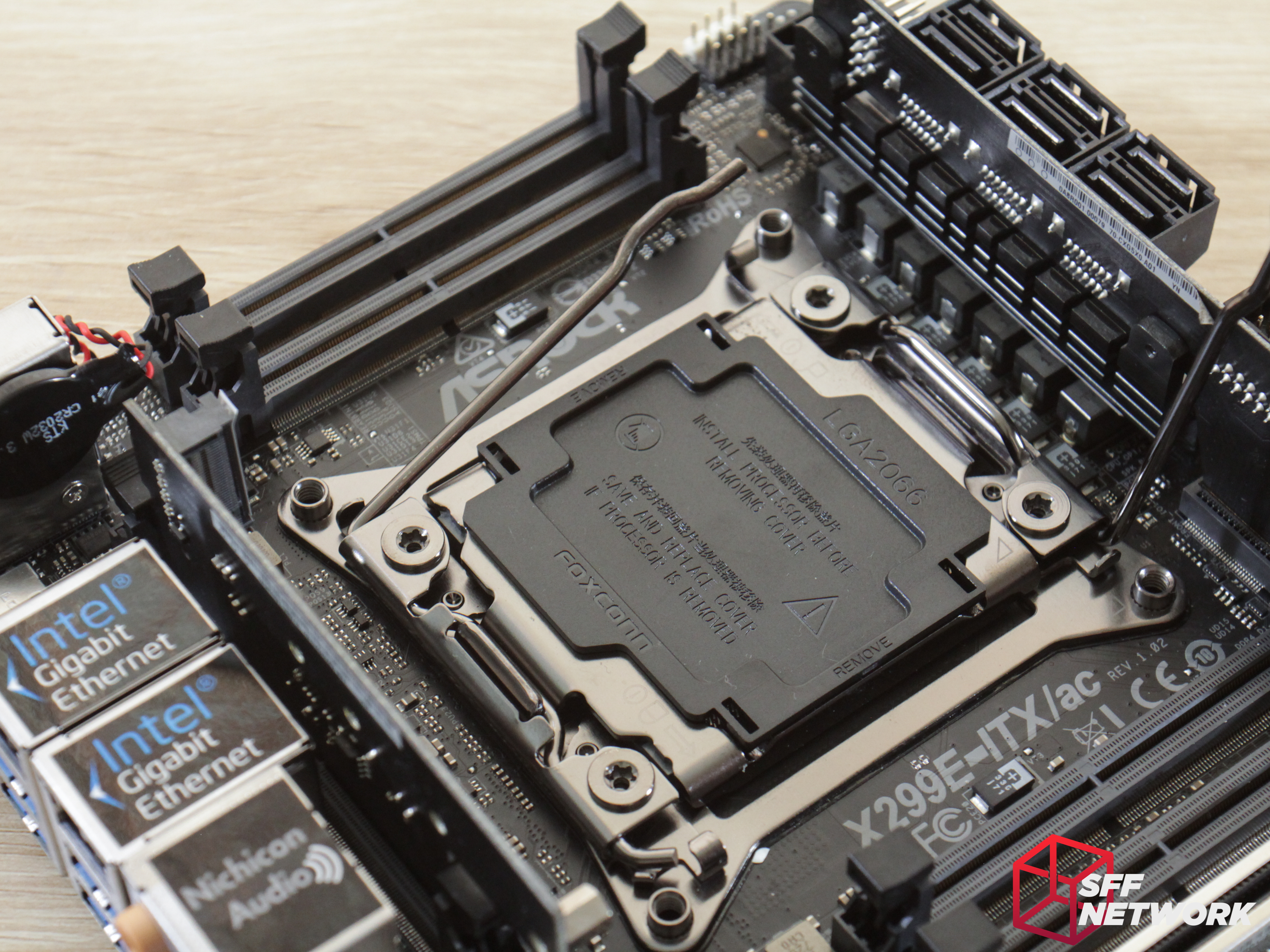
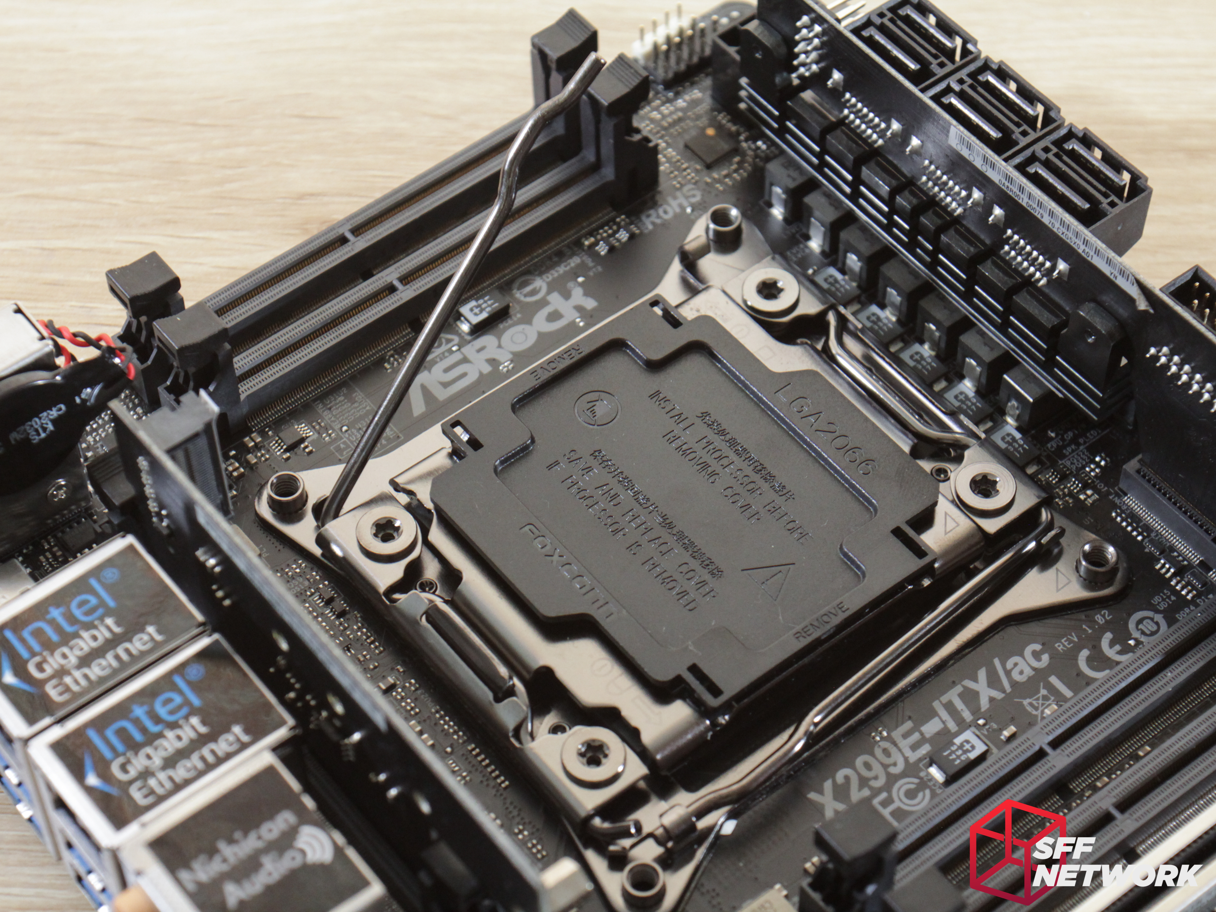
With the first arm opened, the second arm is released, and the retention plate is freed.
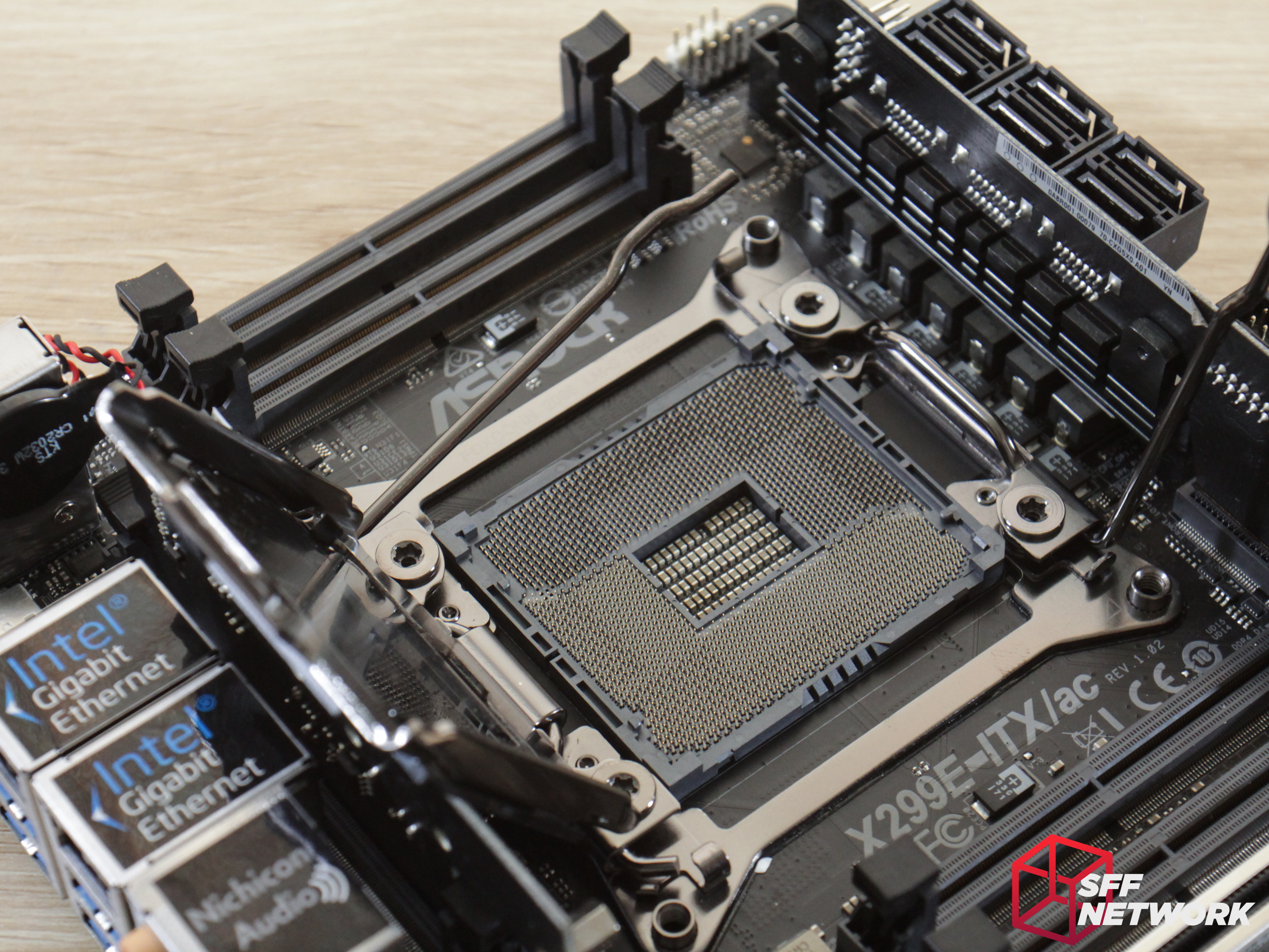
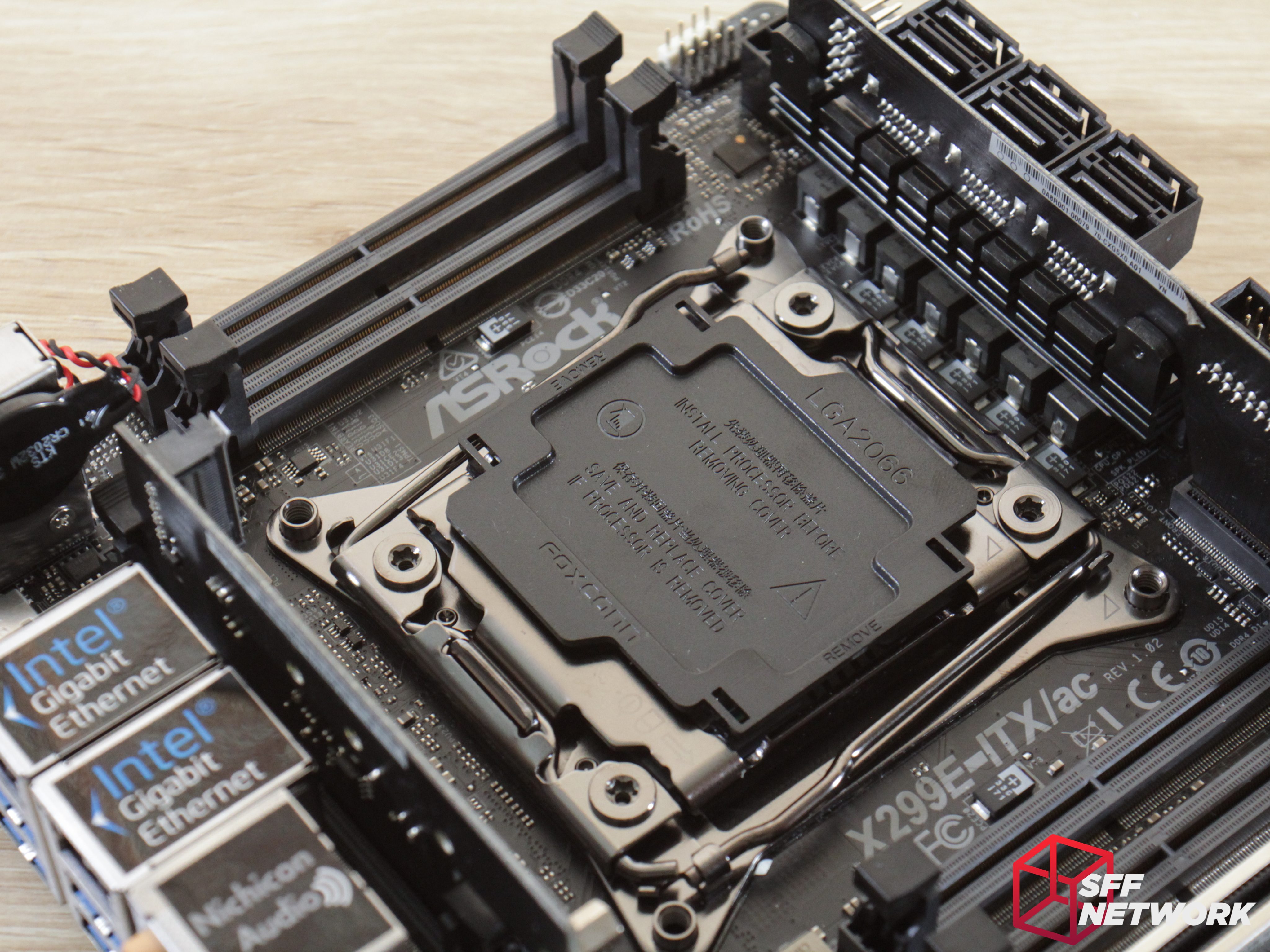
Two thousand and sixty six, yes, 2066, PGA pins are laid out carefully before you. Not the biggest of LGA sockets, but not small by any means, this is Intel’s current HEDT platform socket, which is designed for Kaby Lake-X and Skylake-X. However, the X299E-ITX/ac only supports the Skylake-X variants.
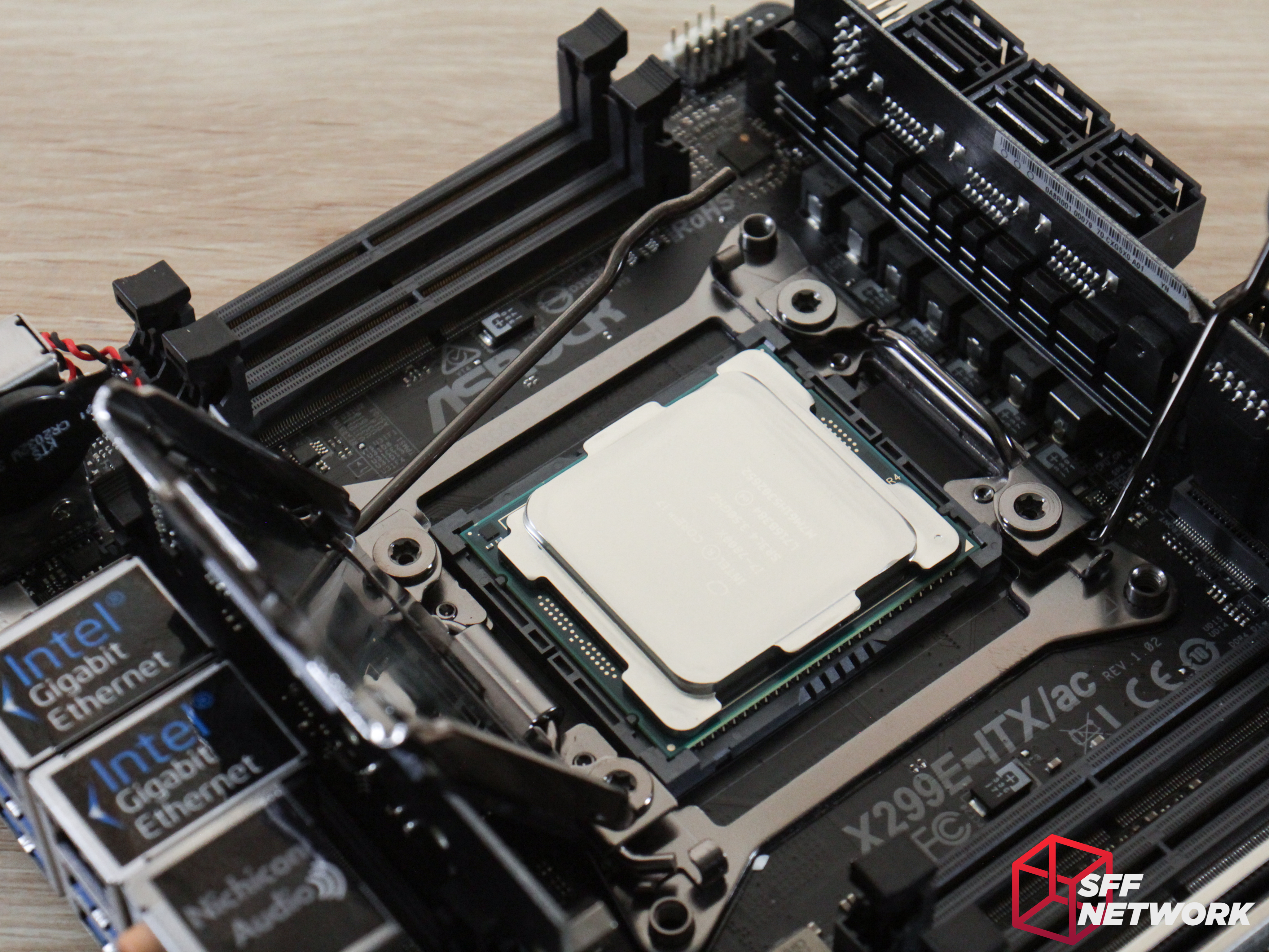
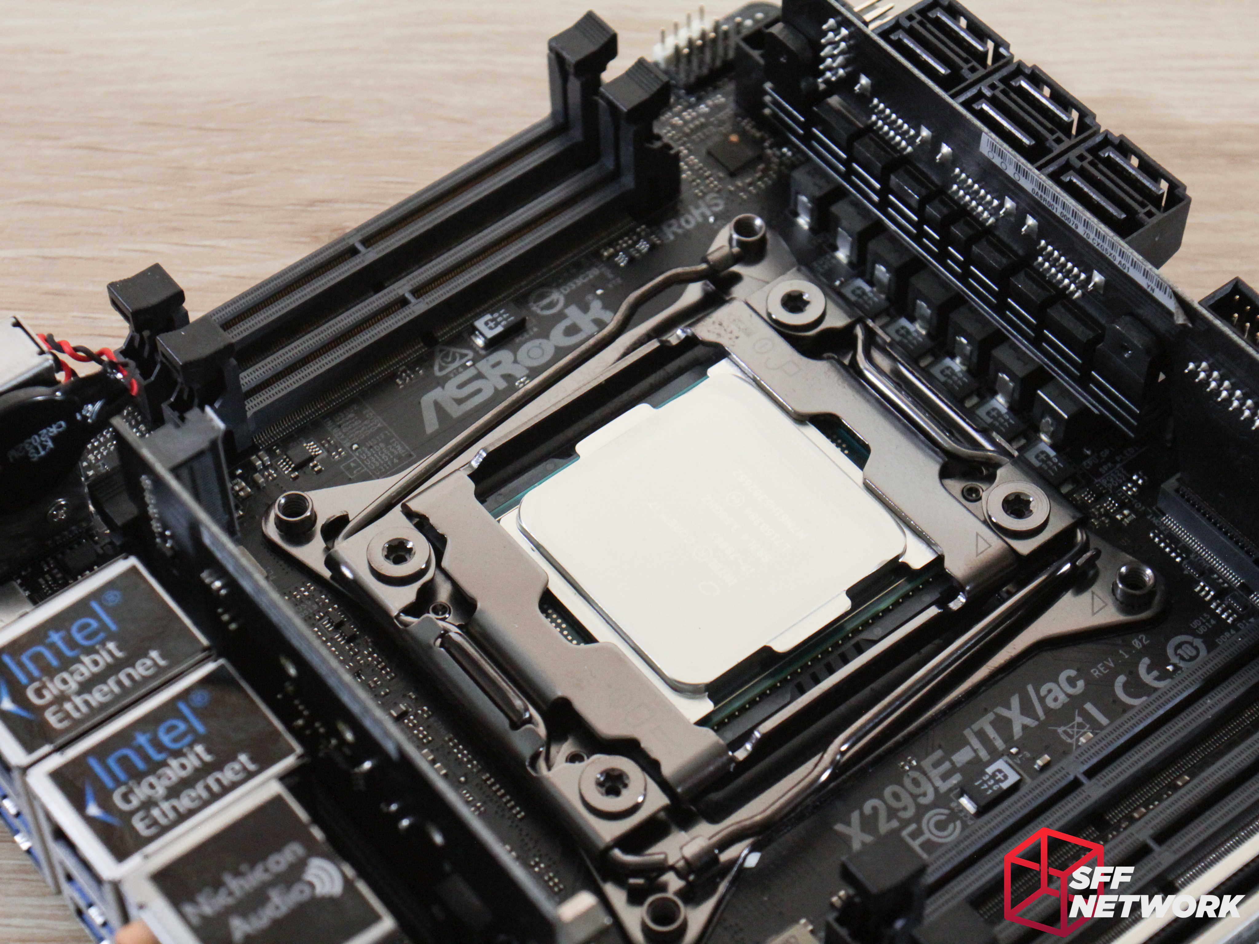
In goes our Intel i7-7800X hex core processor, based on the Skylake-X core. Due to the ‘special’ decisions at Intel around PCIe lane counts on the lesser Kaby Lake-X processors, ASRock has had to limit the support on this board to the Skylake-X processors only. As you can see, the sheer magnitude of expansion options and additional controllers on the X299E-ITX/ac necessitates the extra lanes being supplied to it – the board just wouldn’t work with a lesser quantity of PCIe lanes!
Closing the retention plate, we head towards completion of CPU installation.
One arm down..
The other one down…
And we’re done. This Skylake-X i7-7800X, 3.5GHz 6 core at 140W was funded with thanks to our forum subscribers!
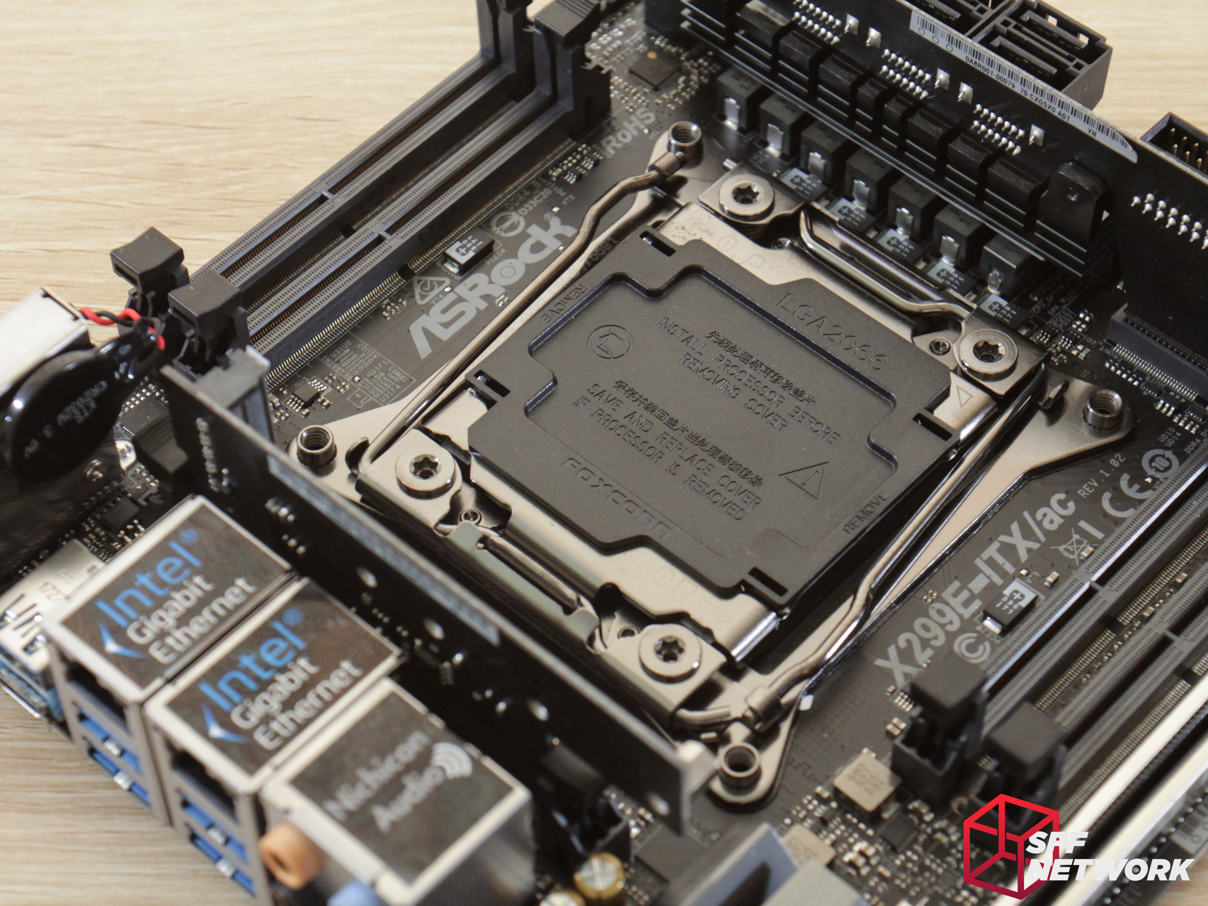
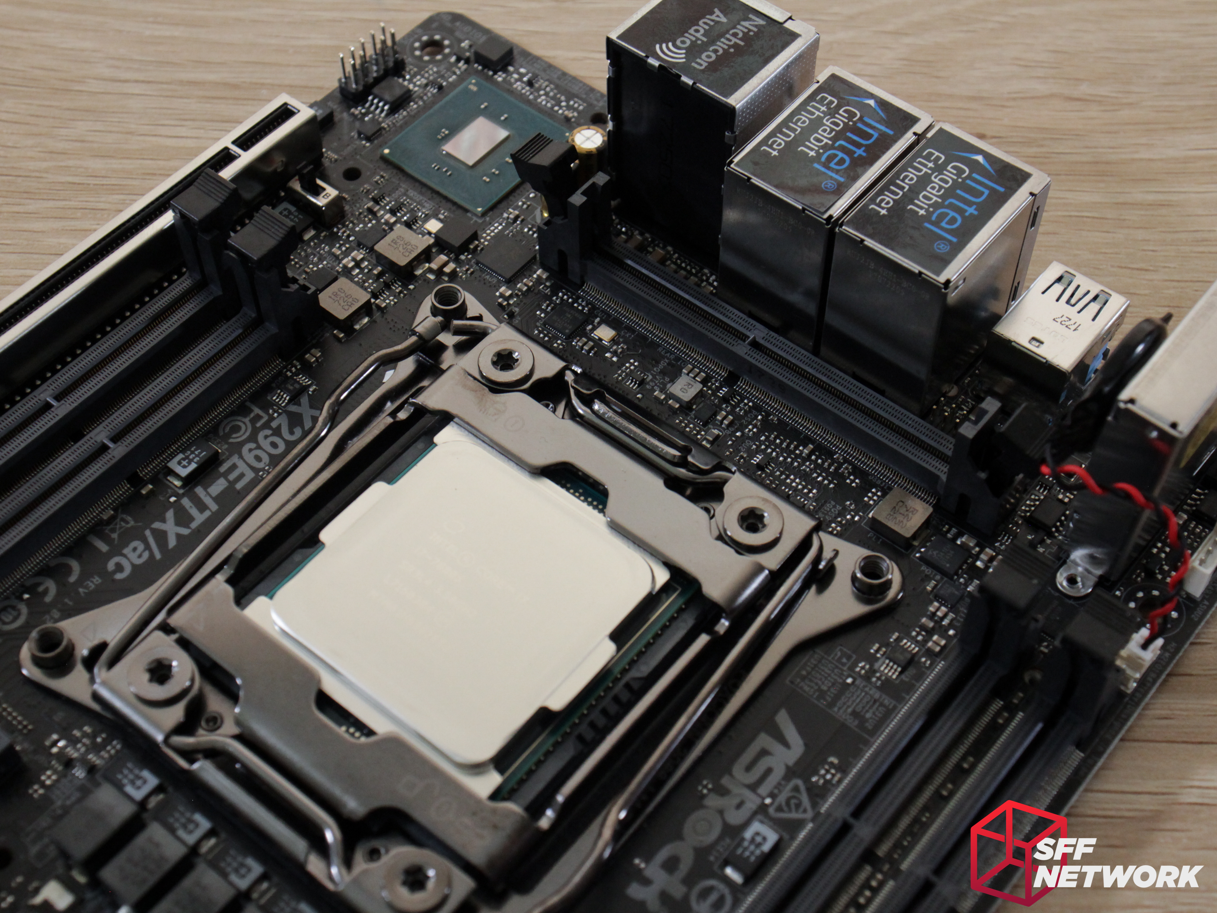
Underneath this subtle grey heatsink is Intel’s X299 chipset! This 6W chip controls many aspects of the LGA2066 platform, and is the successor to Intel’s X99 chipset. Squeezed in between the heatsink and the rear audio stack is the front panel audio header.

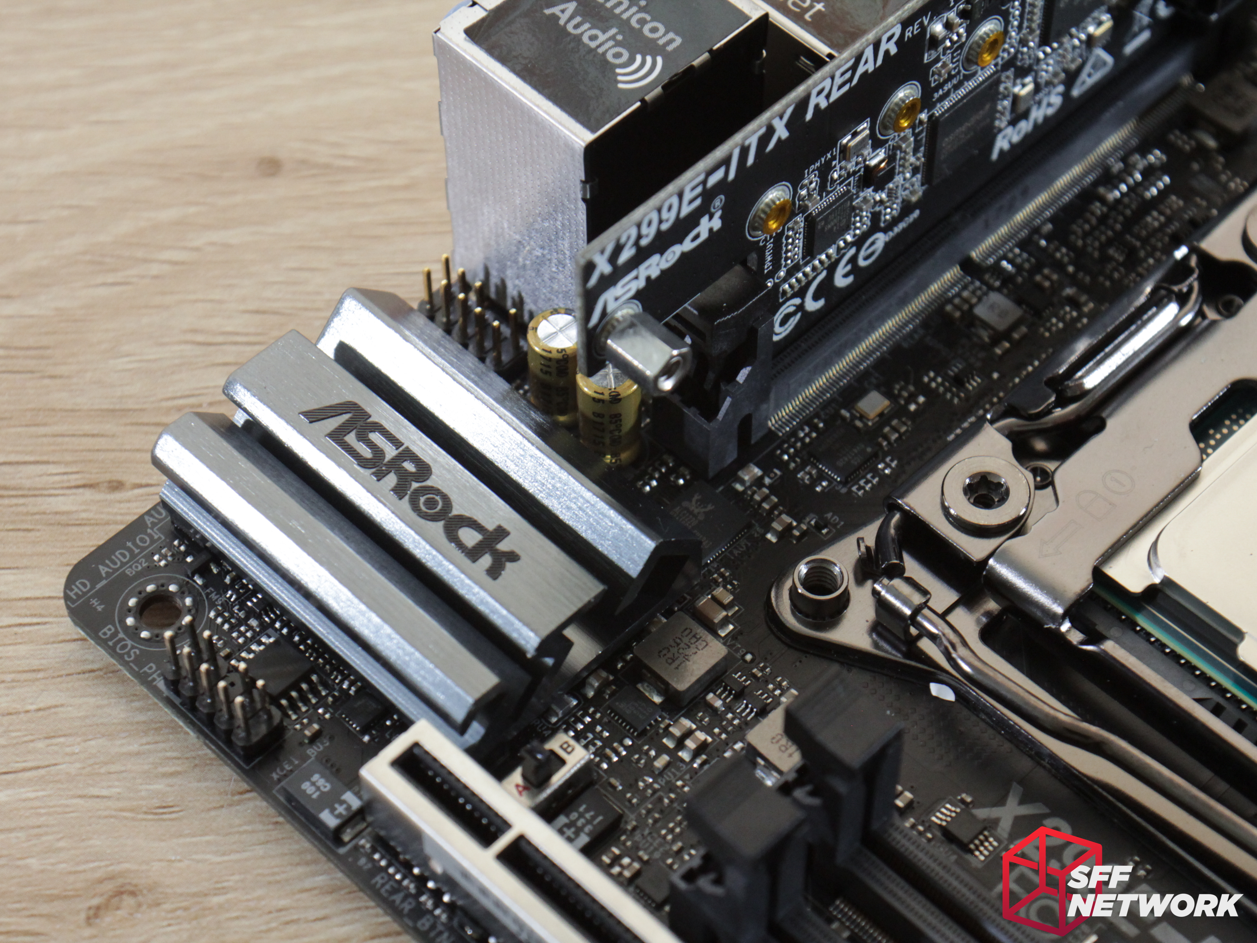
Sneakily hiding next to the chipset heatsink is a small switch – this is related to the tactile button on the rear IO. In position A, the rear button functions as a clear CMOS switch. Moving the switch to position B changes the button to function as a power on switch – handy for testing purposes, and for those building custom cases without any front ports or switches! The square IC package between the heatsink and rear daughterboard slot is the Realtek ALC1220 audio CODEC. Further to the right is an ICS 6V41742B clock generator, added to enhance the overclocking stability of the motherboard. or so says Google!

As is now the norm for modern M-ITX, the CMOS backup battery is connected by a cable and mounted to the side of a rear IO module. This module in particular is the M.2 based WiFi module, an Intel Wireless-AC 8265 based unit. To the left of the WiFi module is the aforementioned tactile button! The square IC sitting at the tip of the LGA2066 ILM is an Intersil ISL69138, a PWM controller of sorts.

Towards the front of the board, at the top, sits the 8 Pin EPS power input, an RGB header and the front panel header. Having these at the extremes of the board’s PCB enables much better cable management, a positive spinoff from there literally being no room anywhere else to put them. The chip at the top centre is another Intersil ISL69138.
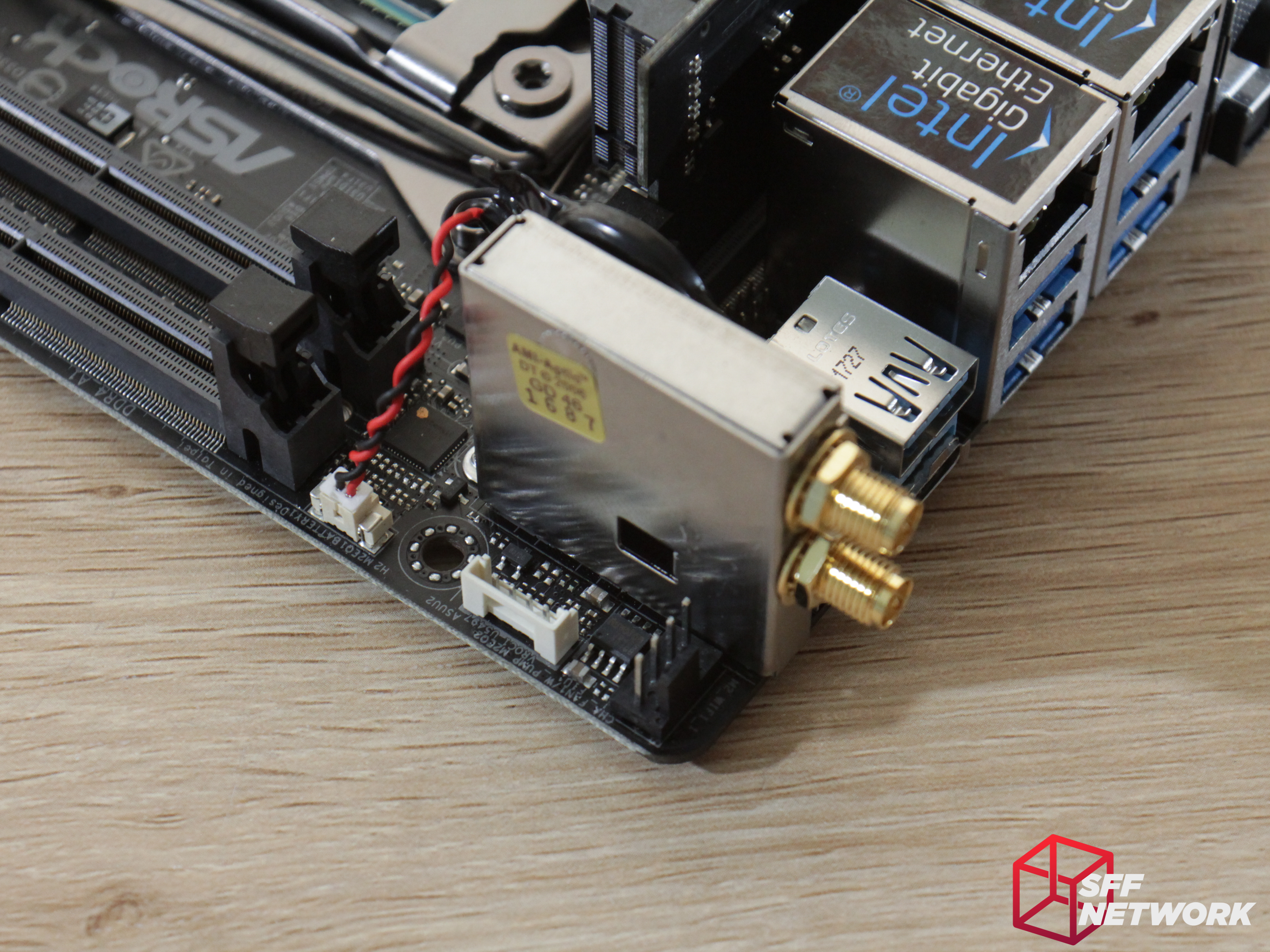
Above the WiFi module sits a 4 pin PWM chassis fan header, and the dastardly Intel VROC header. While I could go into length as to it’s restrictions and whatnot here, I think it is best for you, the reader, to form your own opinion on the matter. Hiding in between is a Nuvoton 3943S, a fan controller IC (couldn’t find a datasheet).
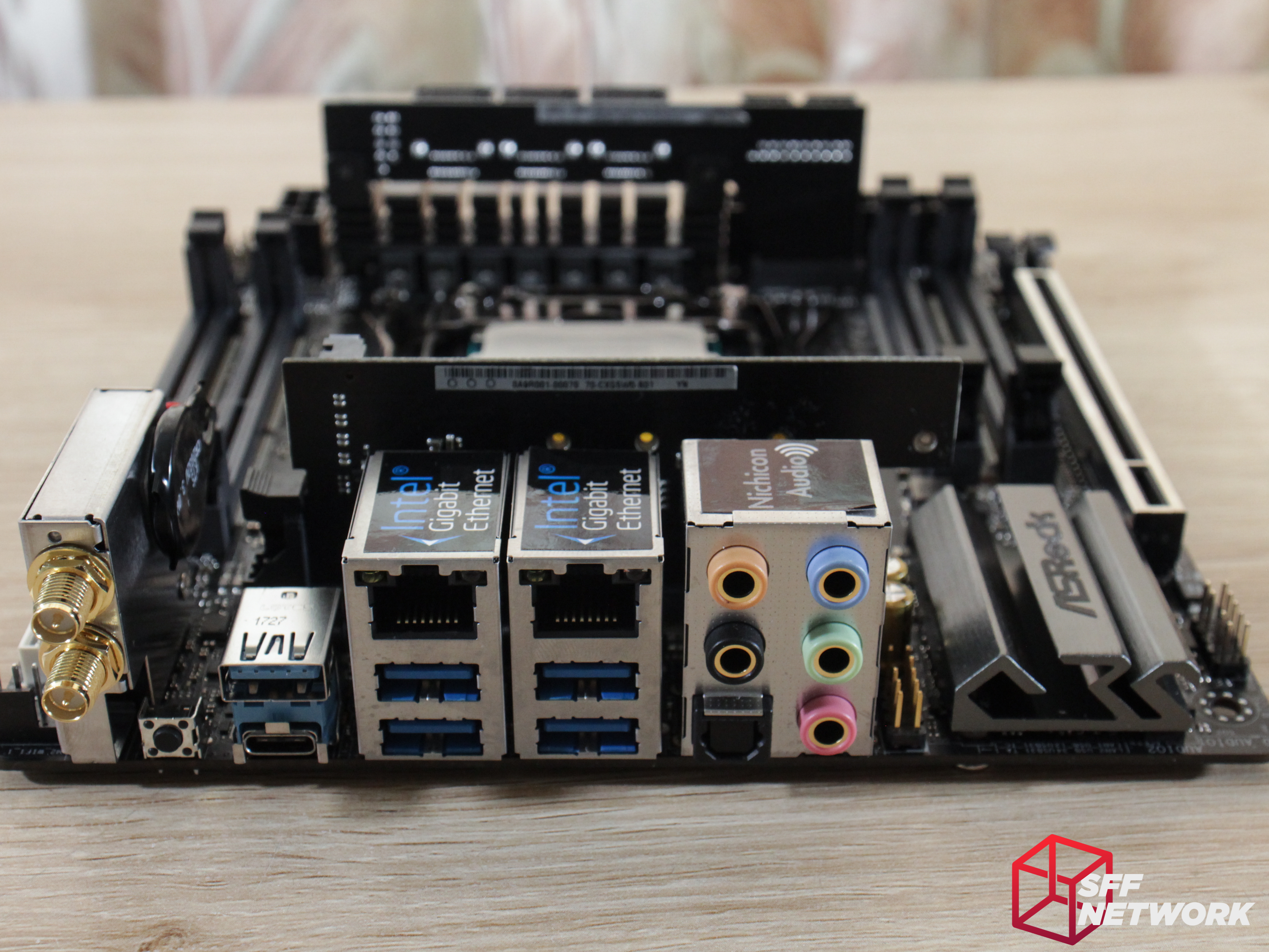
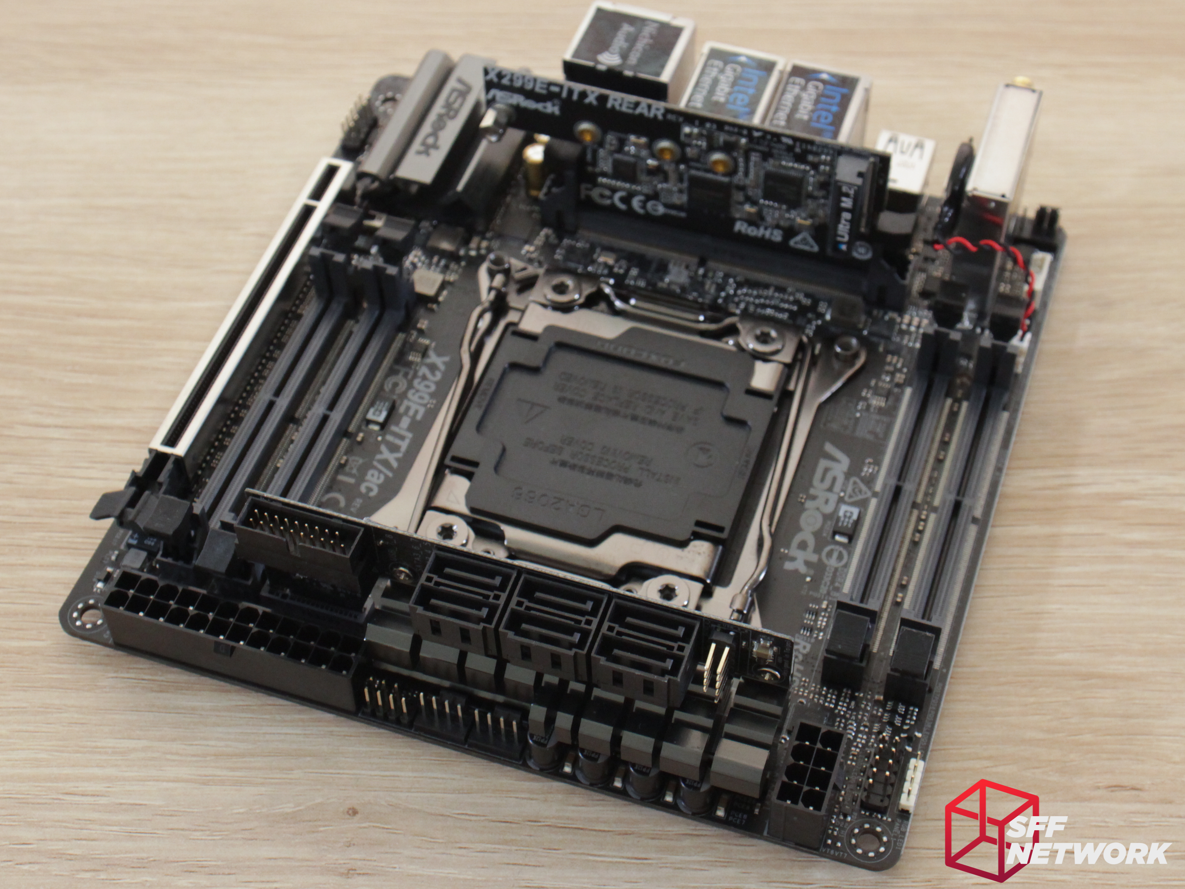
Unlike a certain recently revealed motherboard, the rear IO on the ASRock X299E-ITX/ac has a valid reason for being reduced in breadth compared to the other boards on the market – the chipset had nowhere else to go! Even then, ASRock has managed to stuff quite a bit of IO on here. From the Intel WiFi module, the configurable tactile button, to a pair of USB3.1 Gen 2 ports (one each of Type A and Type C), a four pack of USB3.1 Gen 1 ports, dual Intel gigabit ethernet jacks, 7.1 audio via 3.5mm jacks and finally, an optical audio output. Alas, the USB3.1 Type-C port does not have Thunderbolt, as actually fitting the Thunderbolt controller somewhere on the board, as well as licencing, caused issues for the implementation of this.
The front daughterboard mounts to the VRM heatsink – which is crammed as far forward as possible! Sitting under the heatsink lies the CPU 4 pin fan header, and a second chassis fan header. To the left of these is a secondary front panel header, this one specifically for a power LED and a chassis speaker.
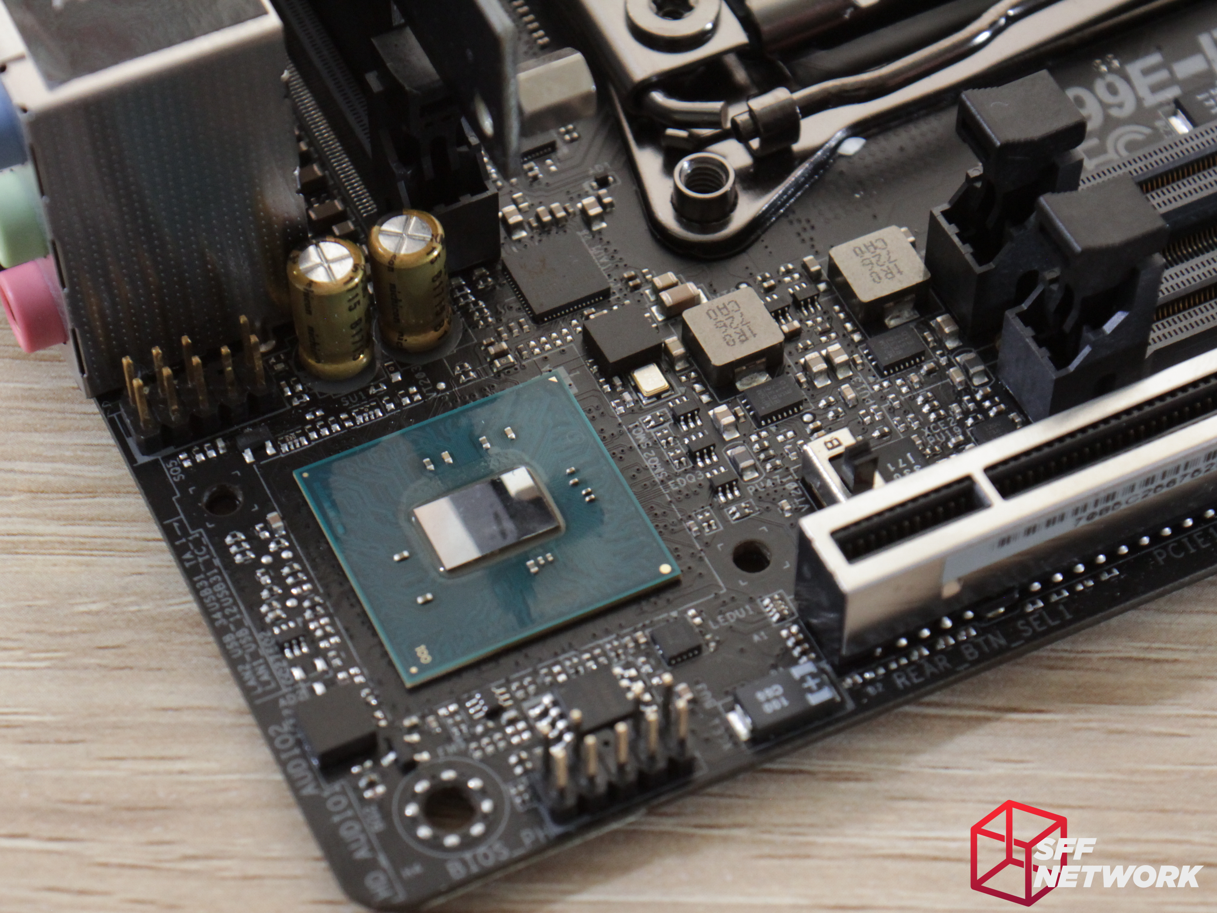
A bare X299! This is a sizeable chip, but as mentioned earlier, only uses around 6 Watts.

Due to this low heat load, the chipset heatsink is pretty simple.
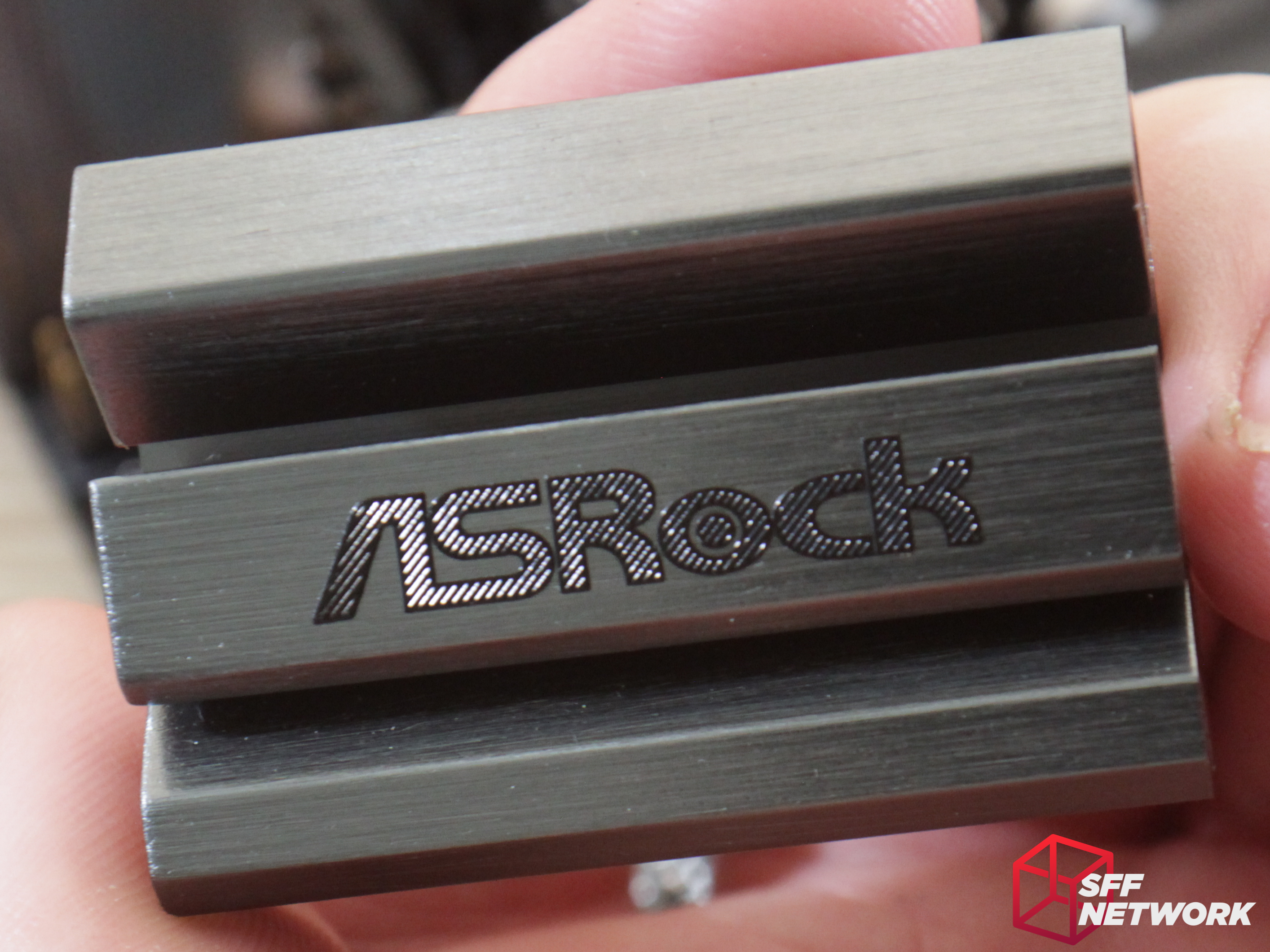
I do like the subtle design though. Ignore my fingernails. You can’t ignore them now can you? Bahahah!
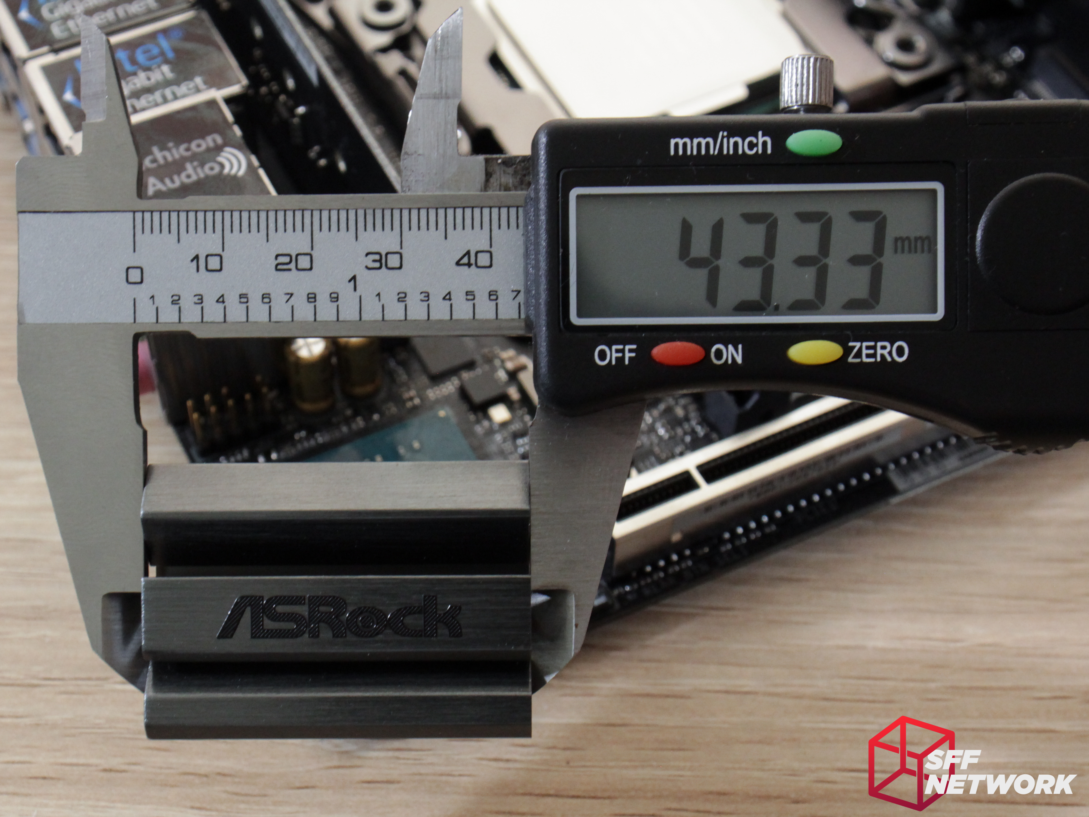
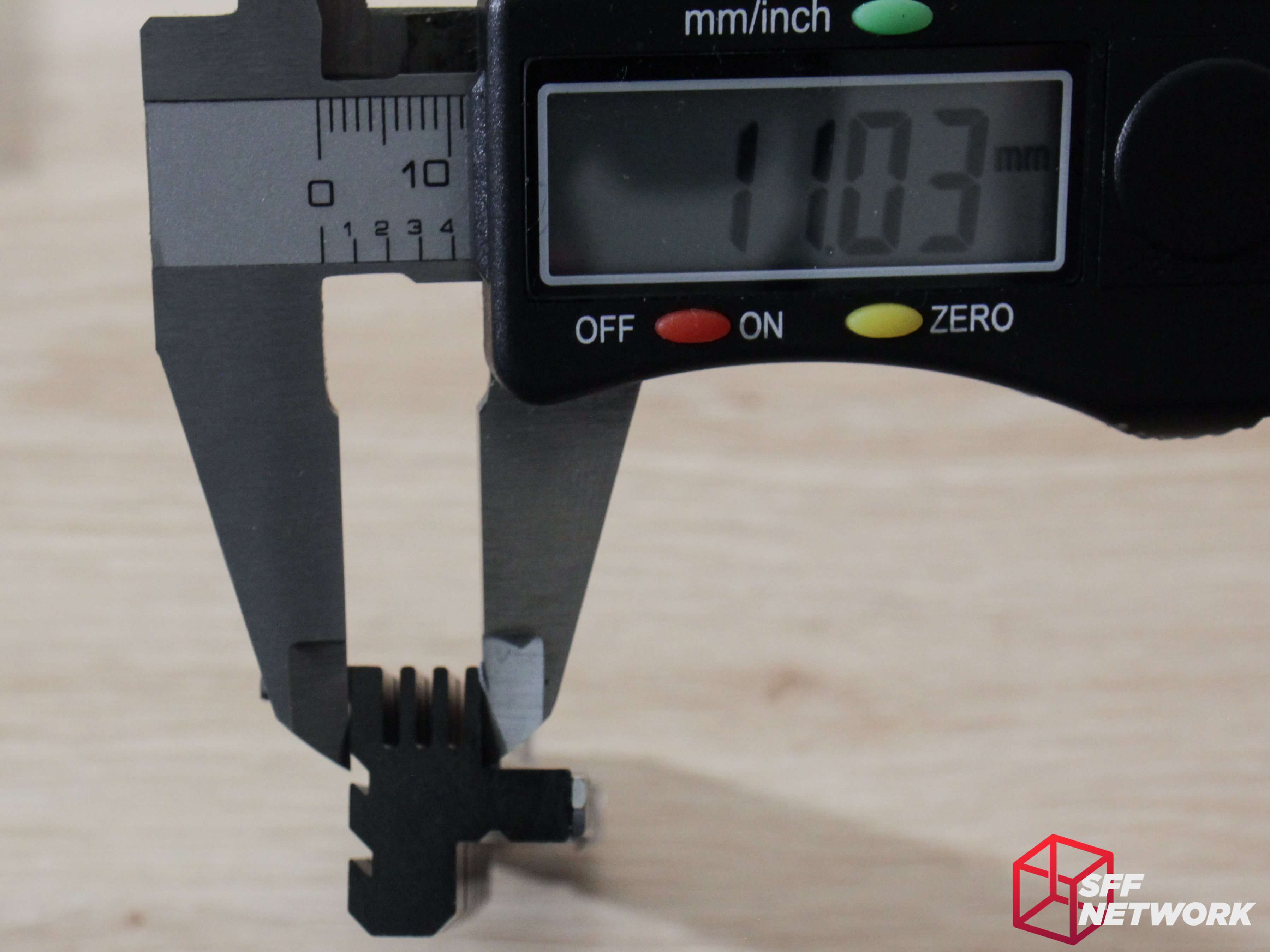
The heatsink is screwed into the board, and measures 43.33mm by…
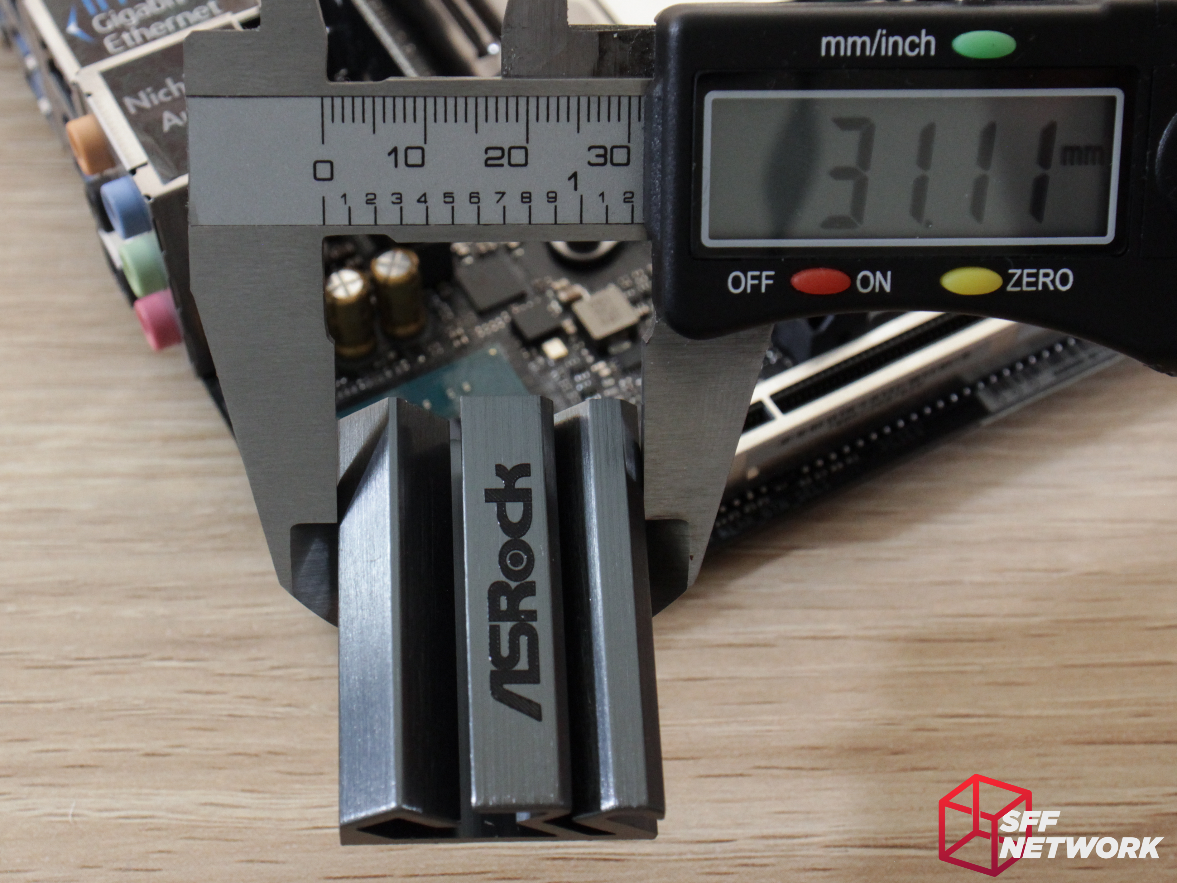
31.11mm.

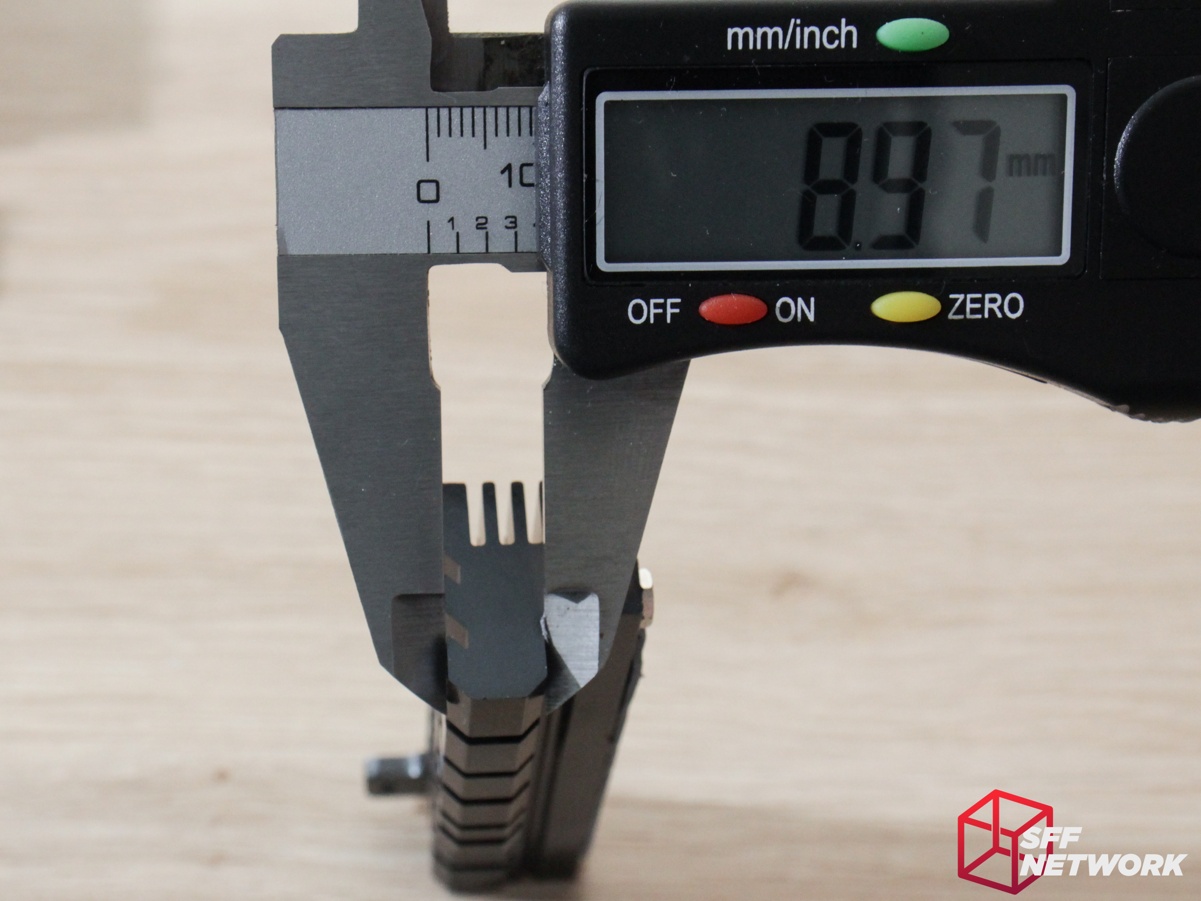
The aluminium is around 1.9mm thick for most of the extrusion.
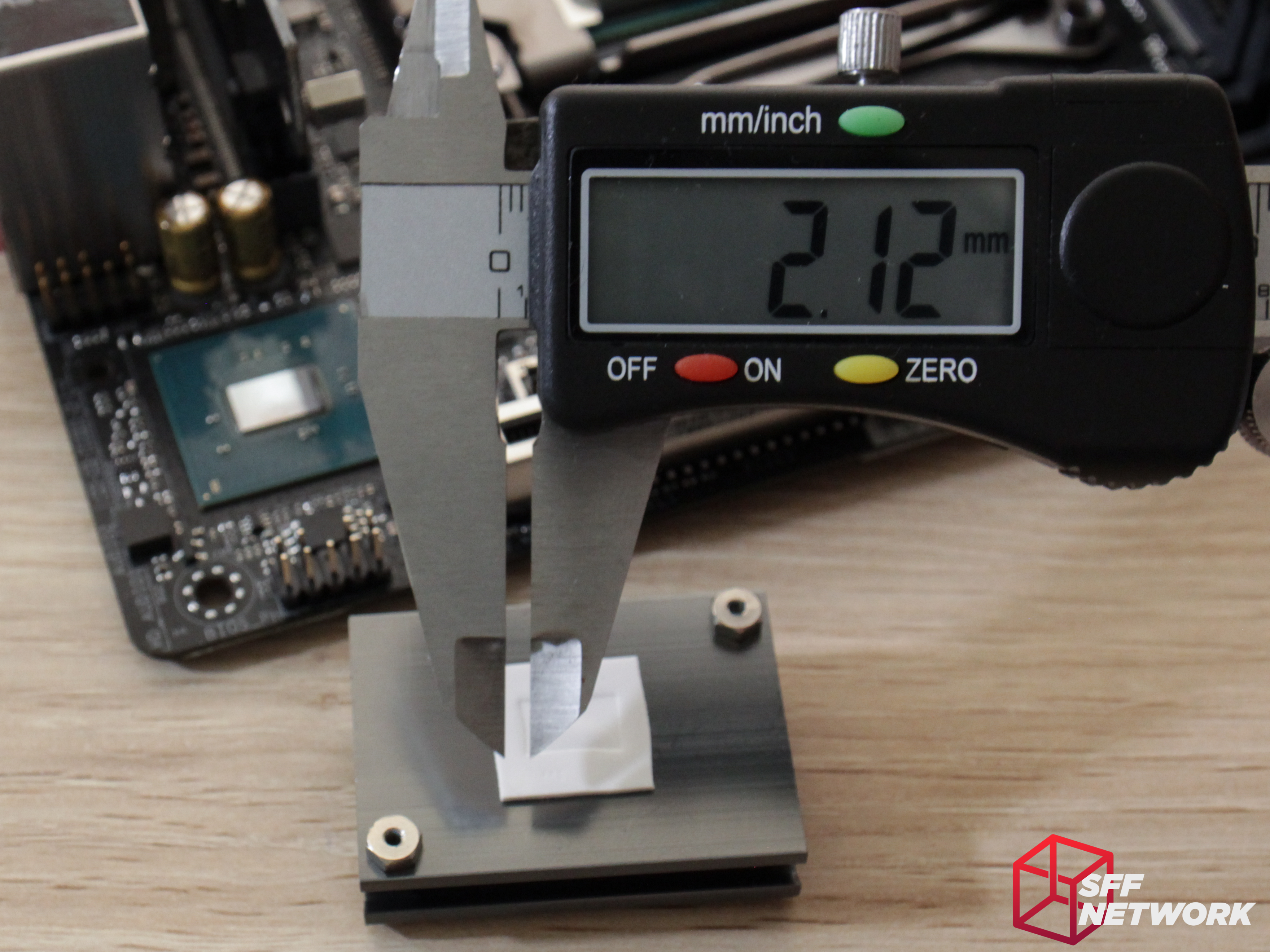
The standoffs keeping the heatsink from crushing the chipset die are around 2.1mm high.
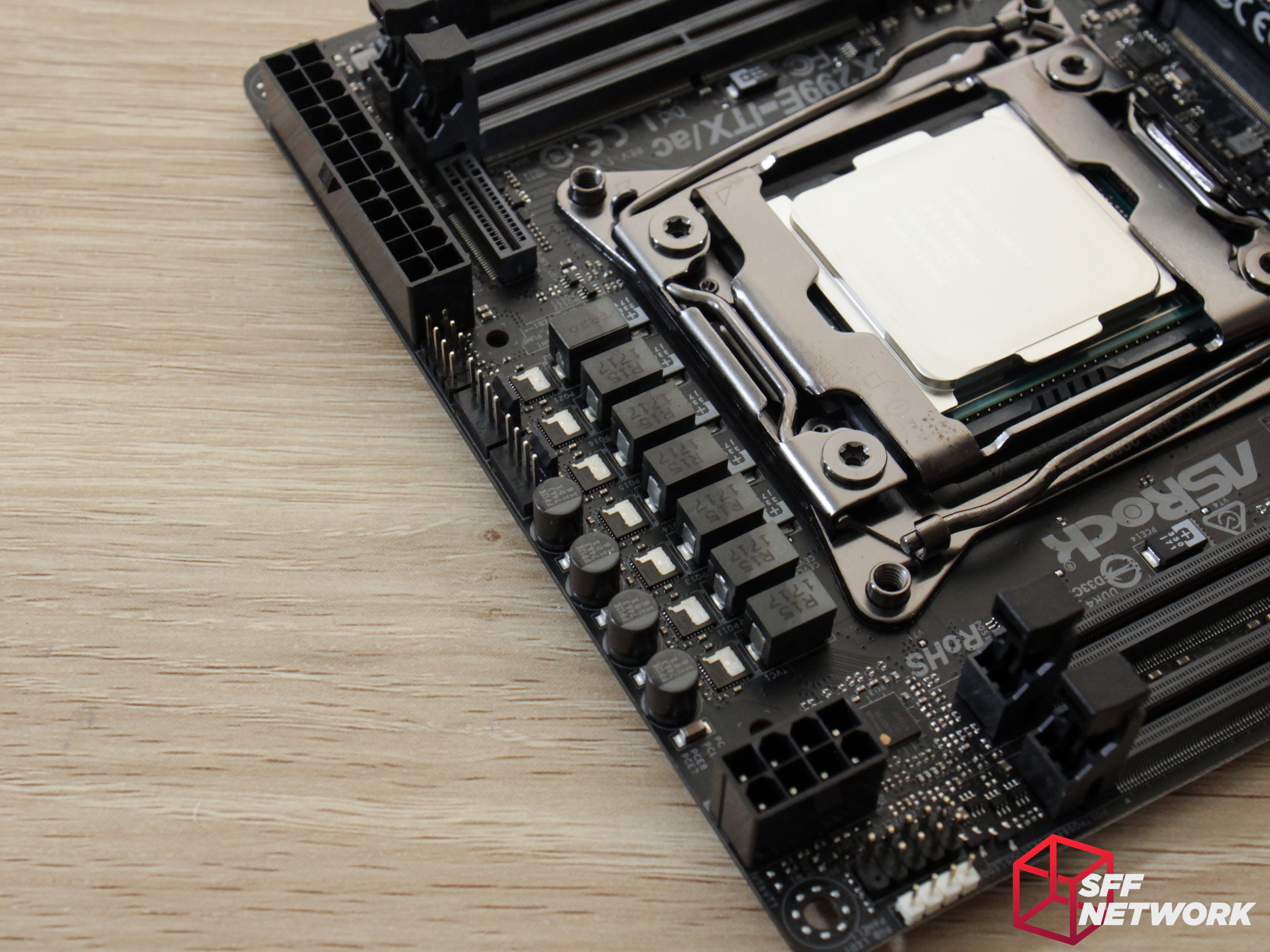
The VRM solution has 7 total phases, using VRMS marked as “23F 73AU” I couldn’t decipher this one. Sorry!
Removing the rear daughterboard reveals the use of a DDR4 SODIMM slot for the connection – however this doesn’t mean you can just add a 5th SODIMM, sorry!
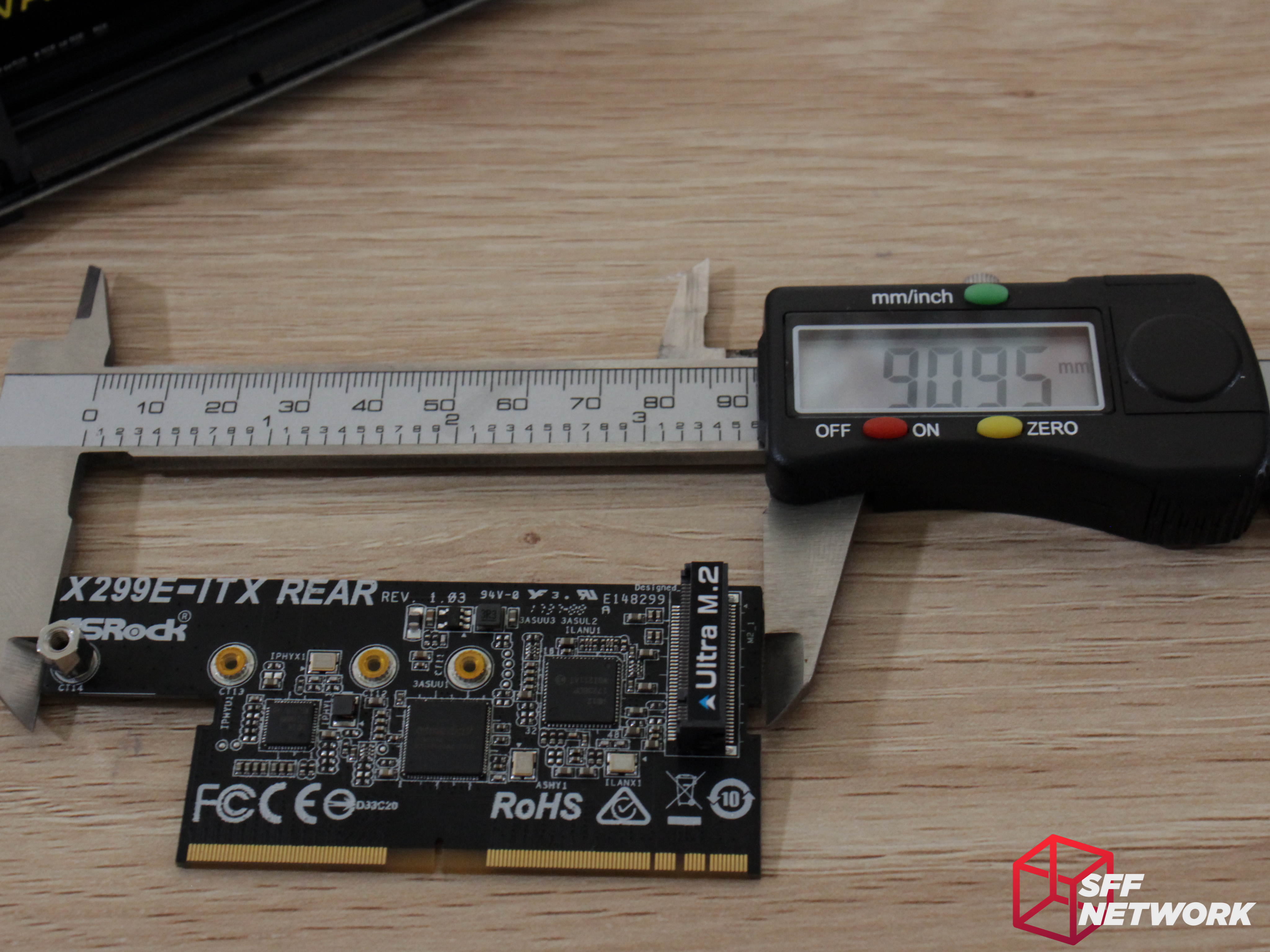
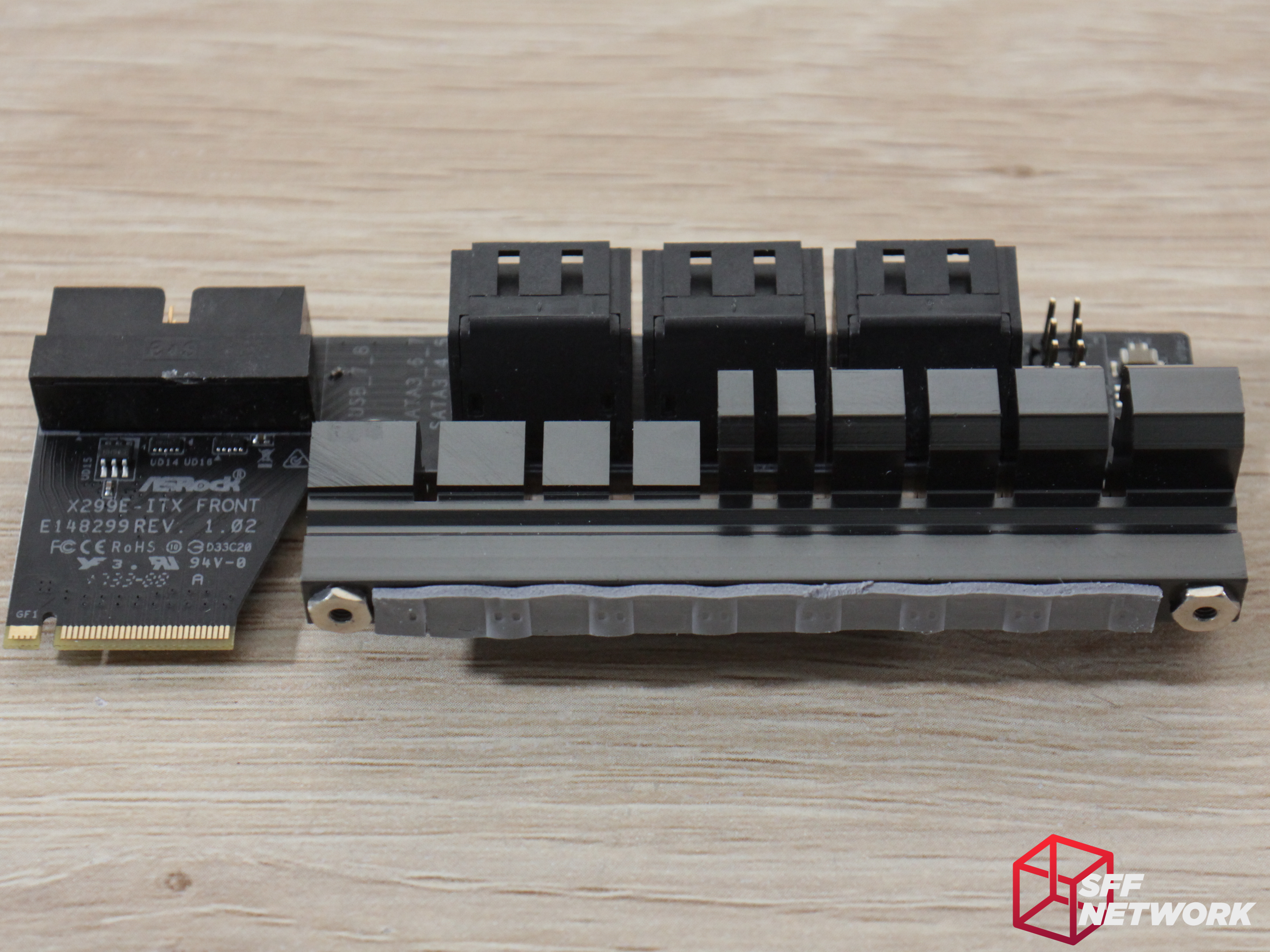
The rear daughterboard is a sizeable unit, being around 91mm wide,
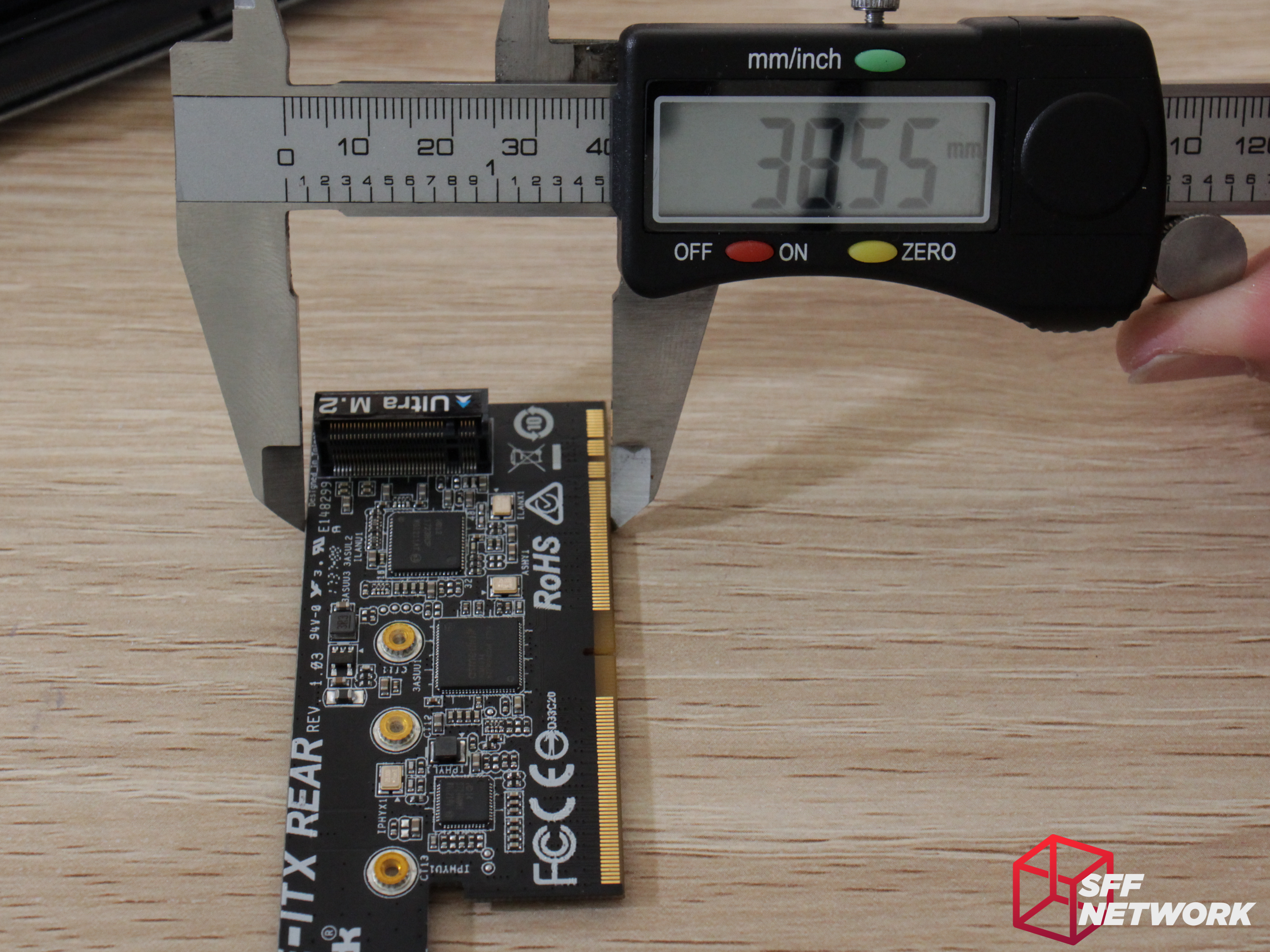
and 38.5mm tall.
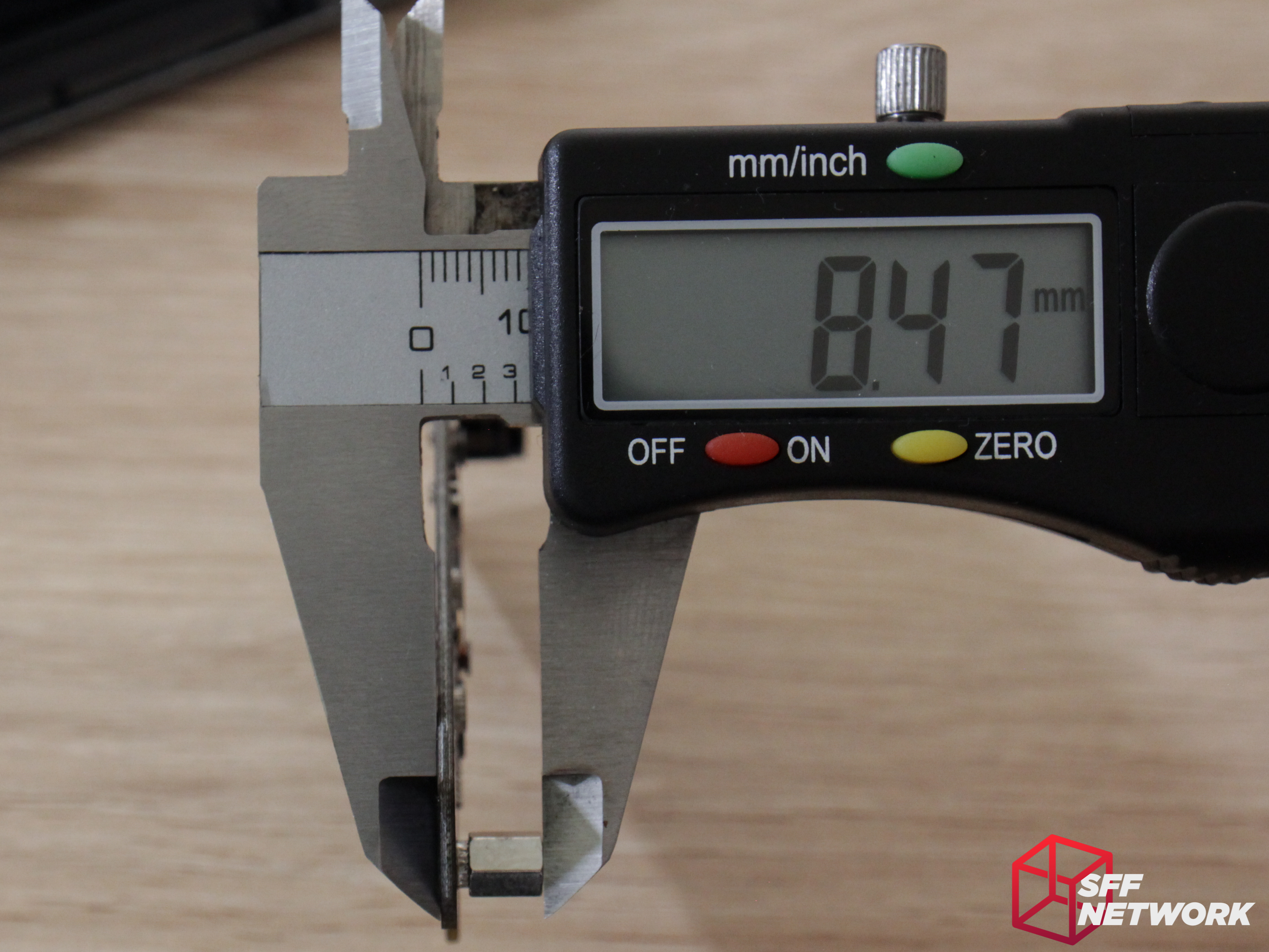
When mounting a M.2 drive on this daughterboard, the drive will be mounted around 8.5mm away from the board, significantly higher than regular M.2 mounting. This is to give breathing room to the two Intel ethernet chips and the ASMedia USB3 controller.
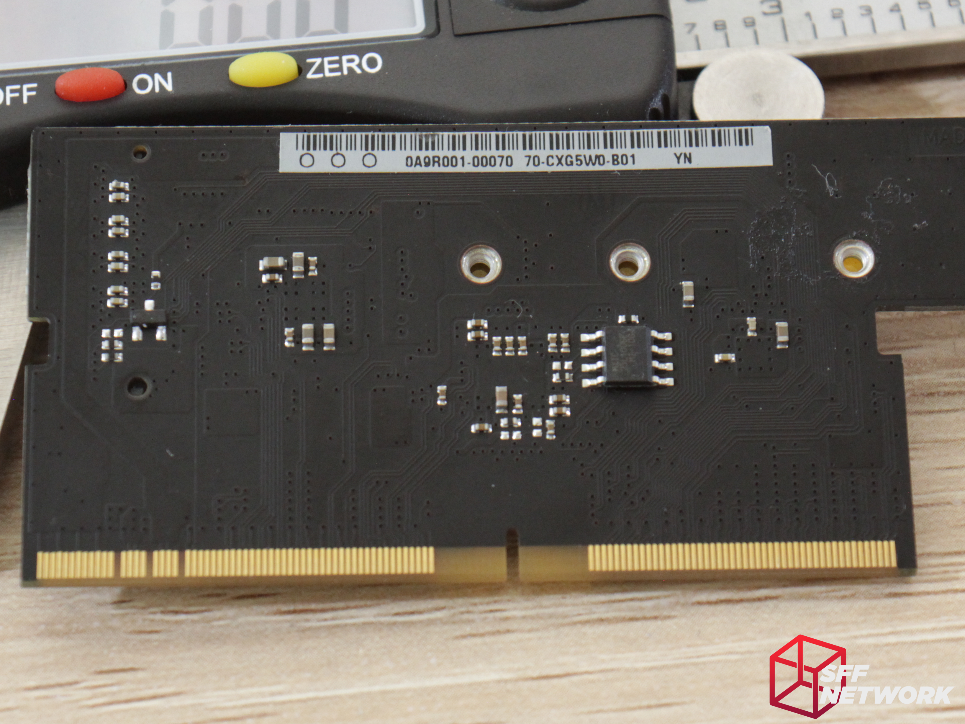
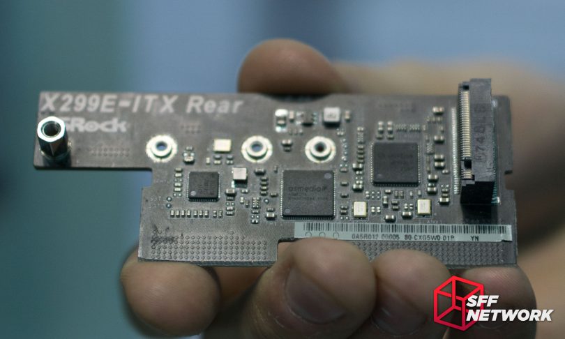
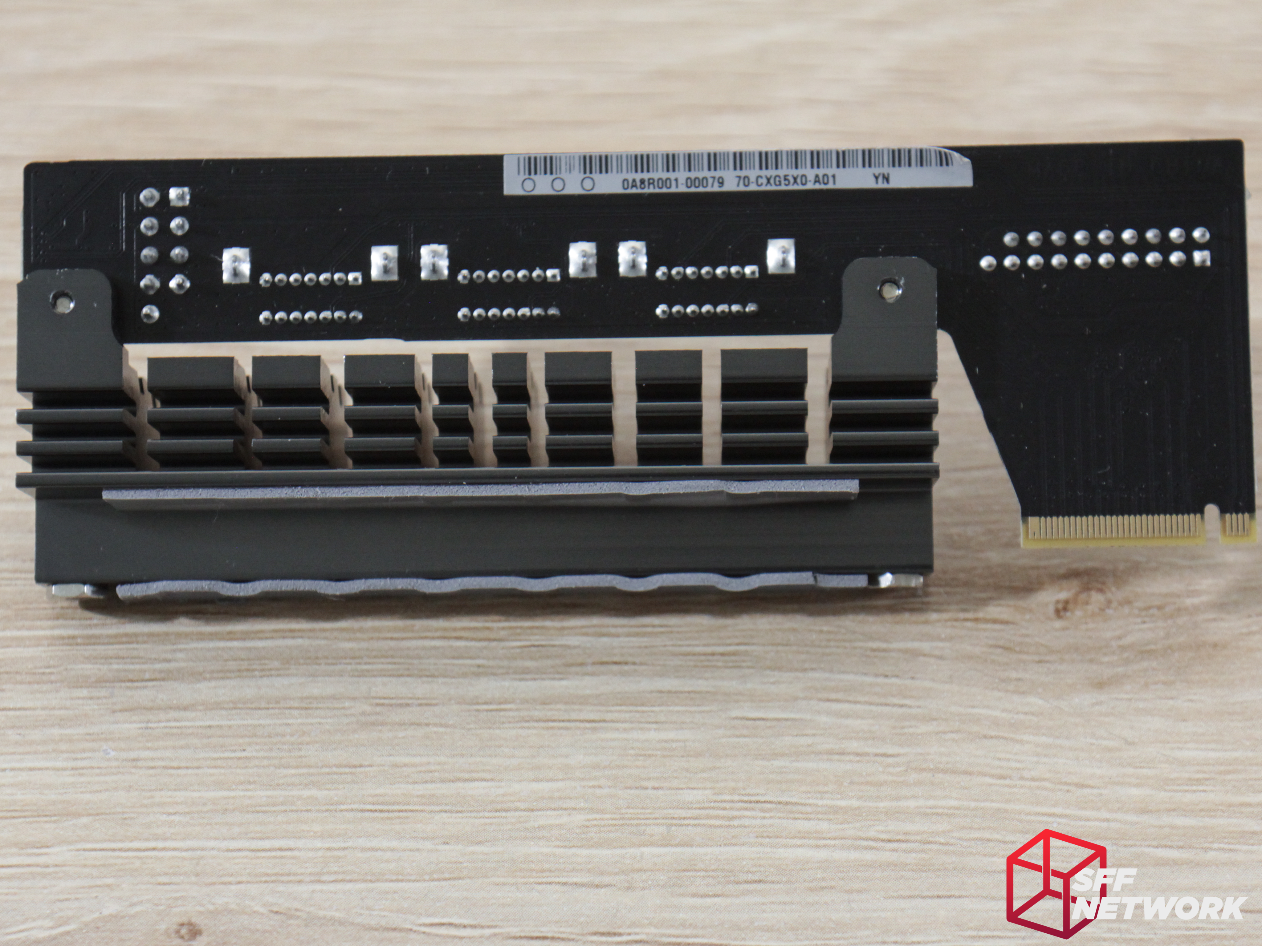
The backside of the daughterboard is pretty bare, with a lone Macronix 23L1006E, a serial flash chip.
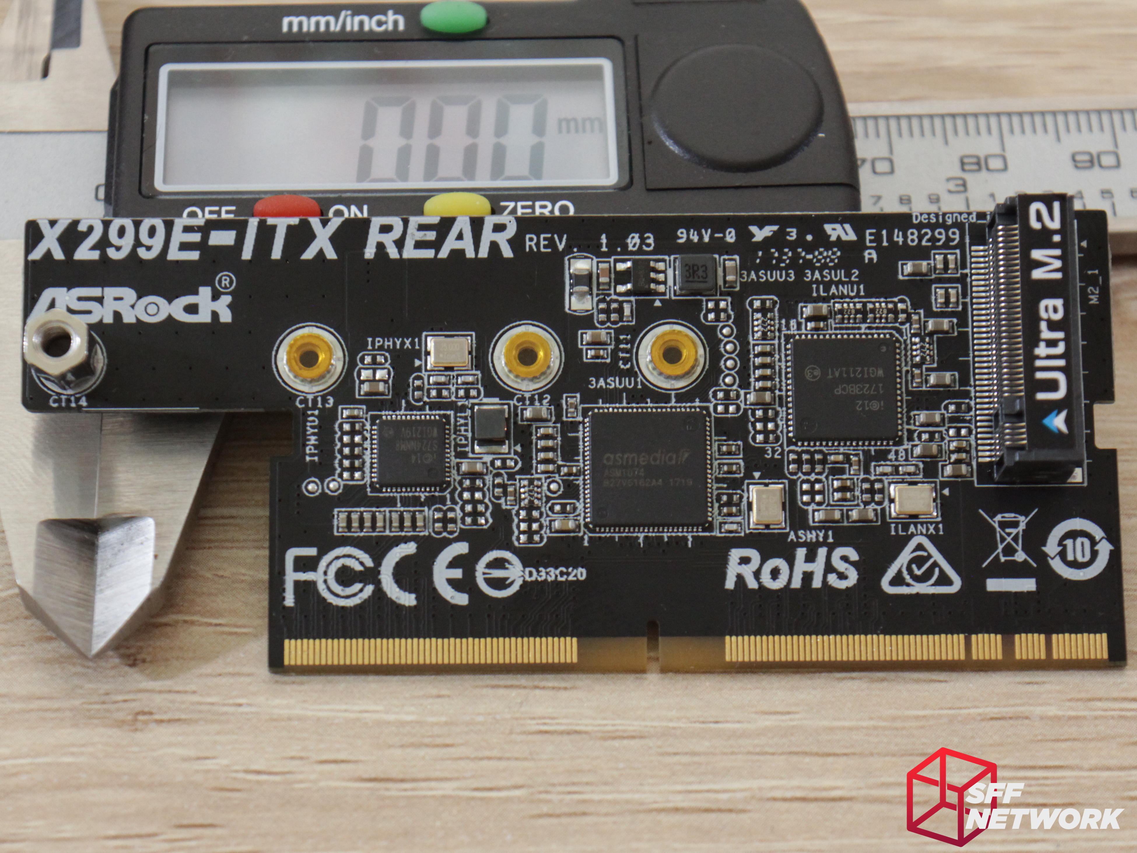
The front of the daughterboard is much more populated. From left to right, the major components are an Intel S724NM8 WG1219V ethernet controller, an ASMedia ASM1074 USB3 controller, and an Intel 1723MCP W1211AT ethernet controller.
The WiFi card uses this M.2 slot for connection with the board.

For those with fancy heatspreader on your RAM, the RAM slots are around 11mm apart.
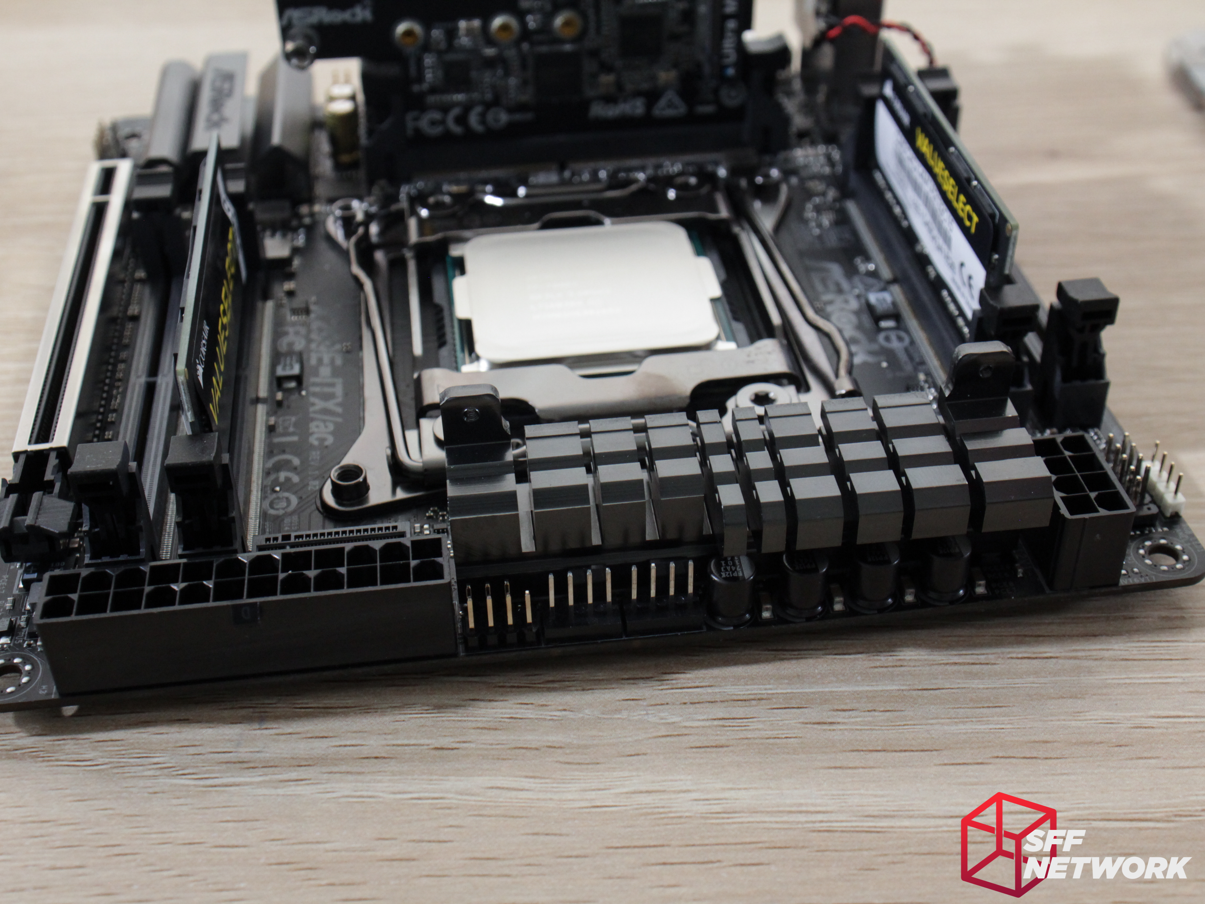
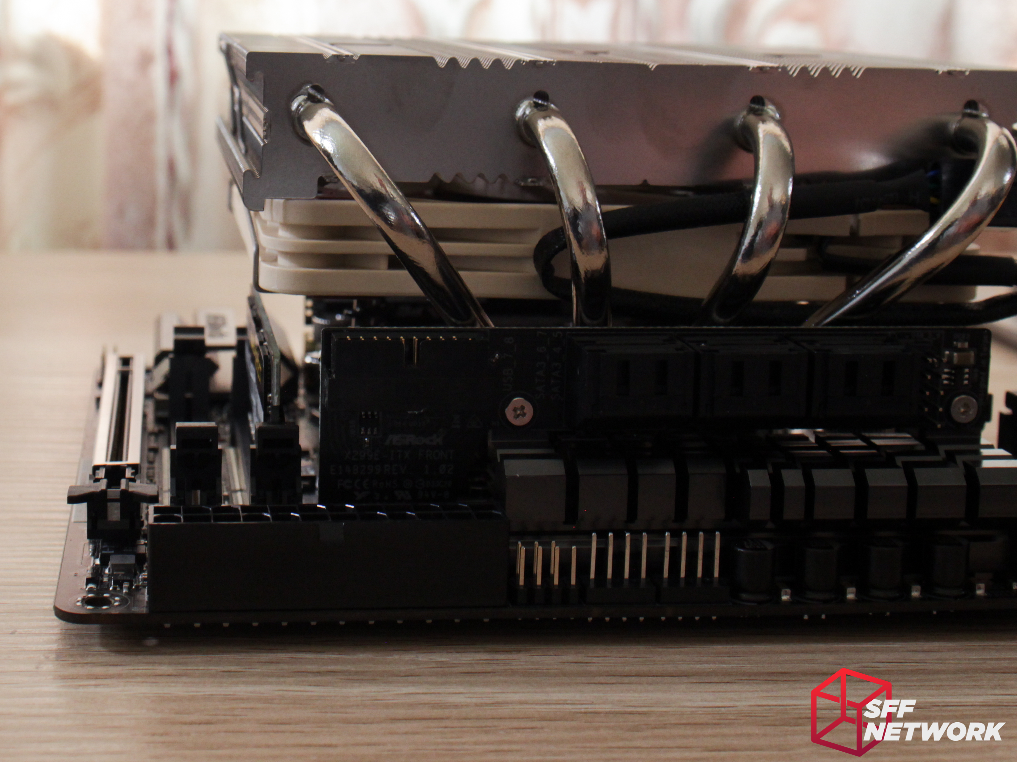
Removing the front daughterboard and heatsink module reveals the sheer mass of the heatsink – that’s a lot of metal on such a small motherboard!
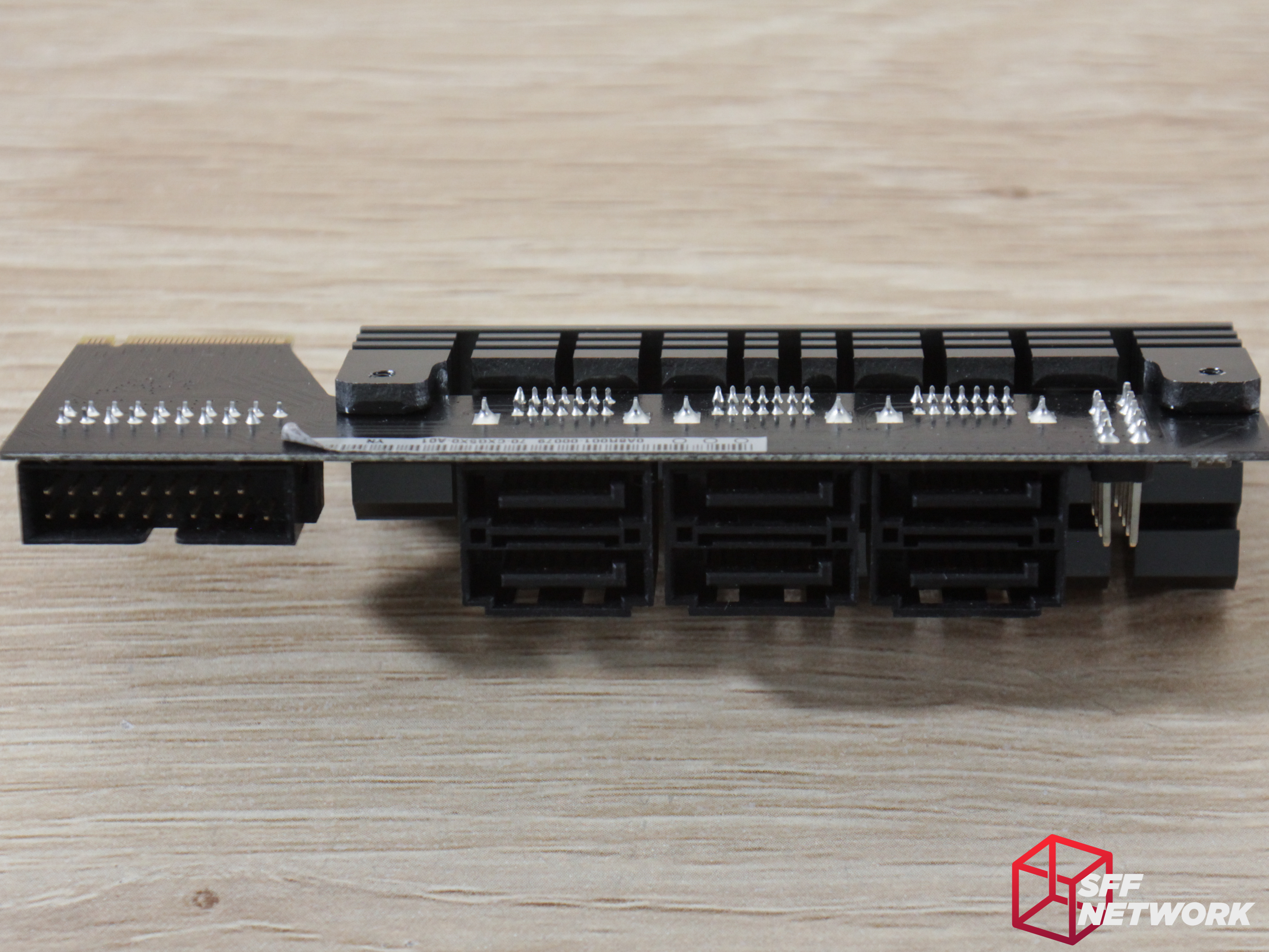
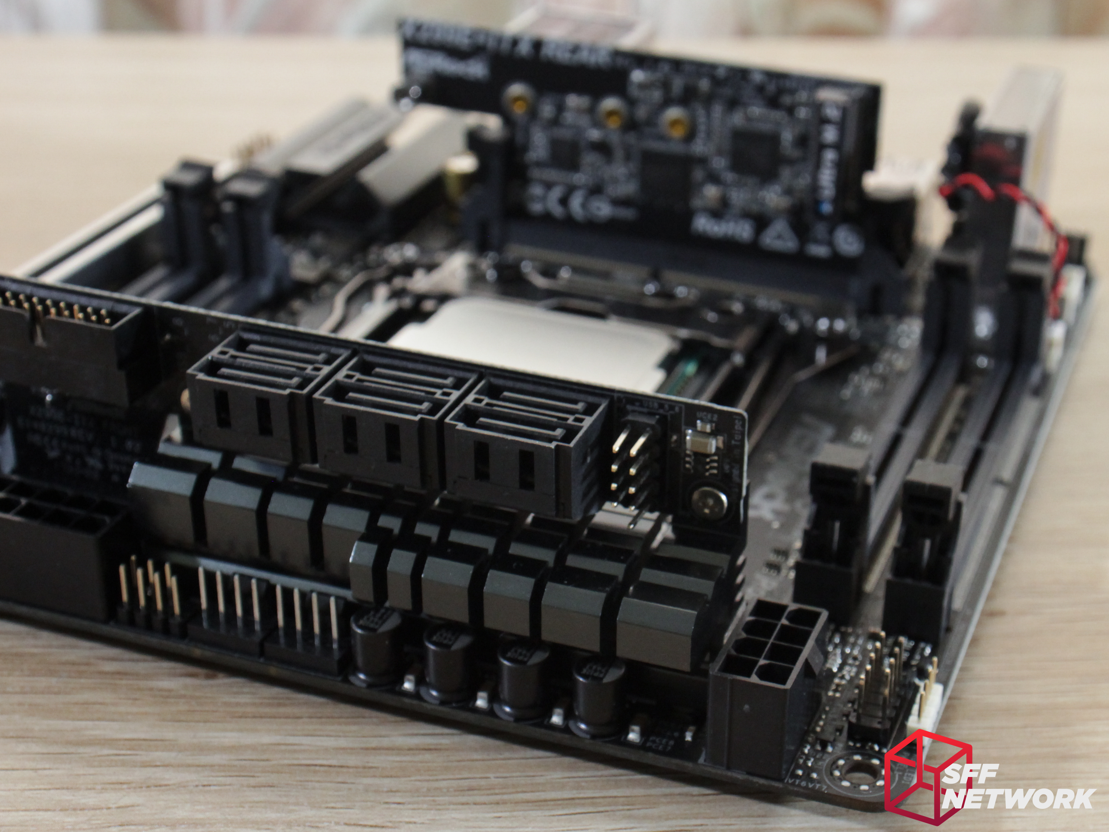
Here we have the front panel USB3.0 header, the six SATA ports and the front panel USB2.0 header. The daughterboard is screw mounted into the VRM heatsink in two places – stabilising the board and retaining it, since its interconnect slot has no retention capability.
Due to the different heights of the VRM chips and the inductors, the heatsink is a two level affair. Thermal pads aid heat transfer on both component types.

Made of extruded and then machined aluminium, the VRM heatsink is 77.8mm wide.
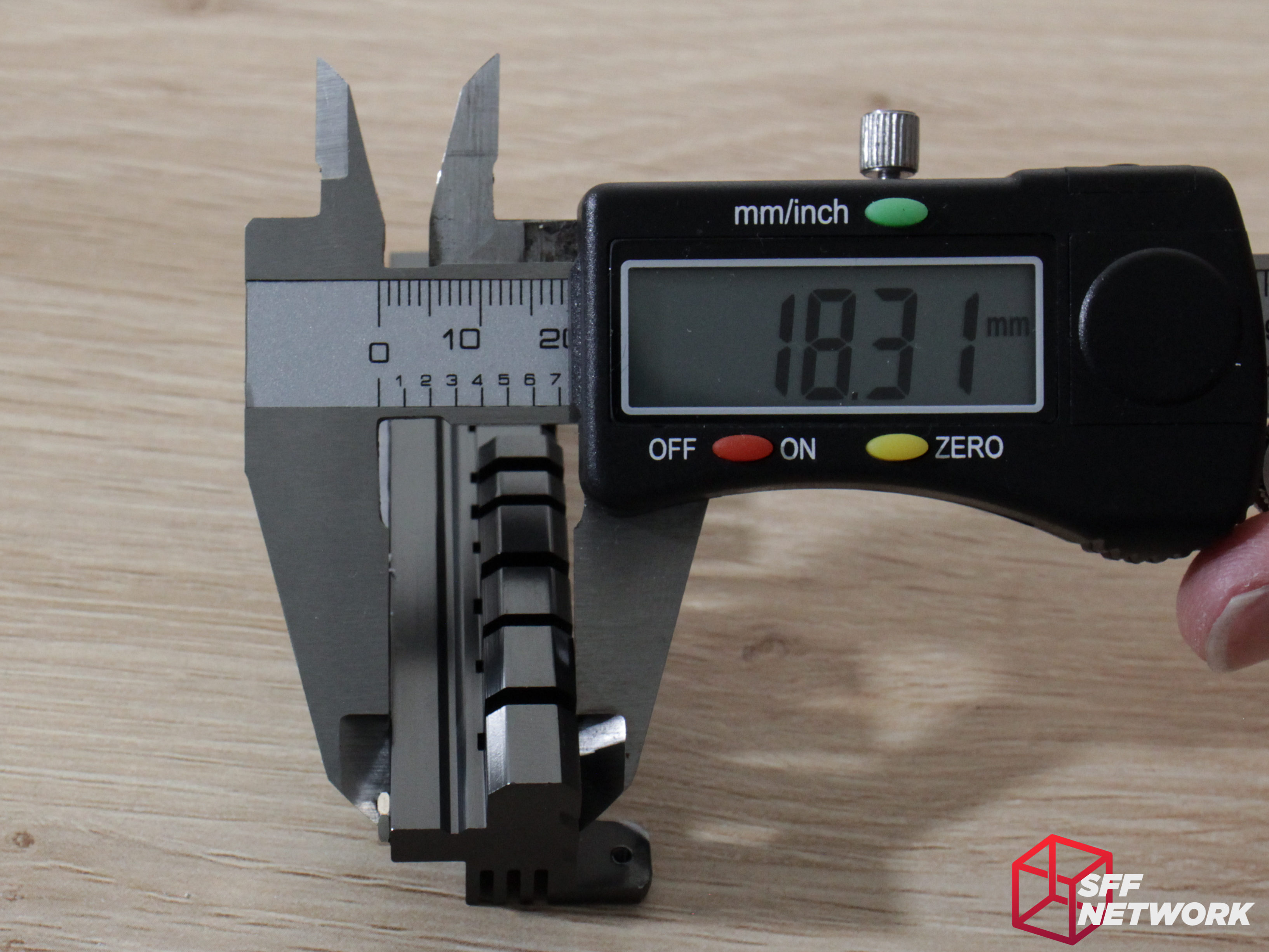
And is 18.3mm tall.
More measurements – this is the VRM chip contact area.
This is a sizeable heatsink.
This is quite a complicated extrusion.
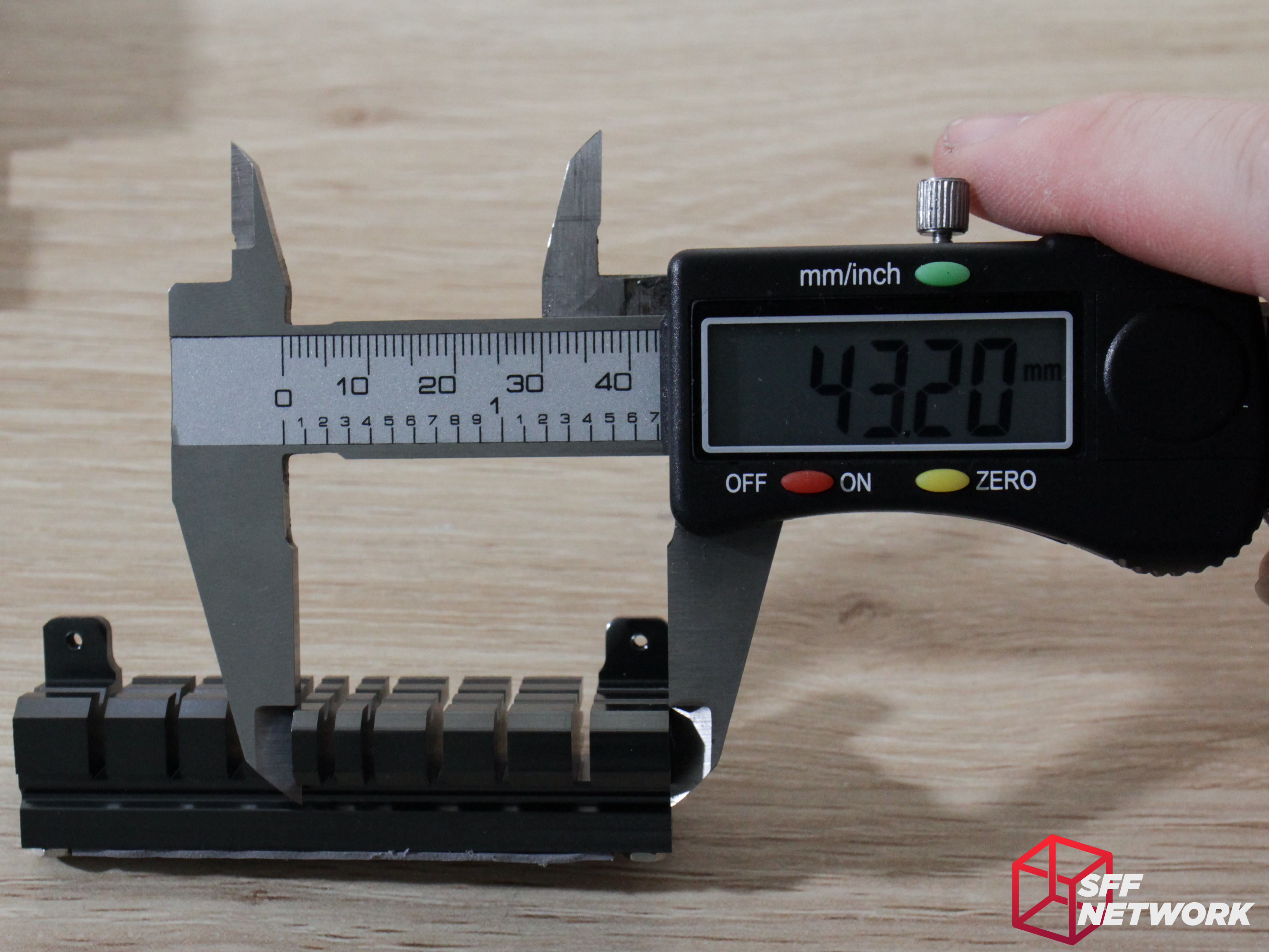
Due to the design of the board, a section is removed to allow access to the fan headers and ATX power connector. What’s left is 43mm long.
Not much going on on this daughterboard apart from ports and a healthy dose of out-of-focus blur.
Minus the daughterboard, airflow to the CPU socket area is a little improved.
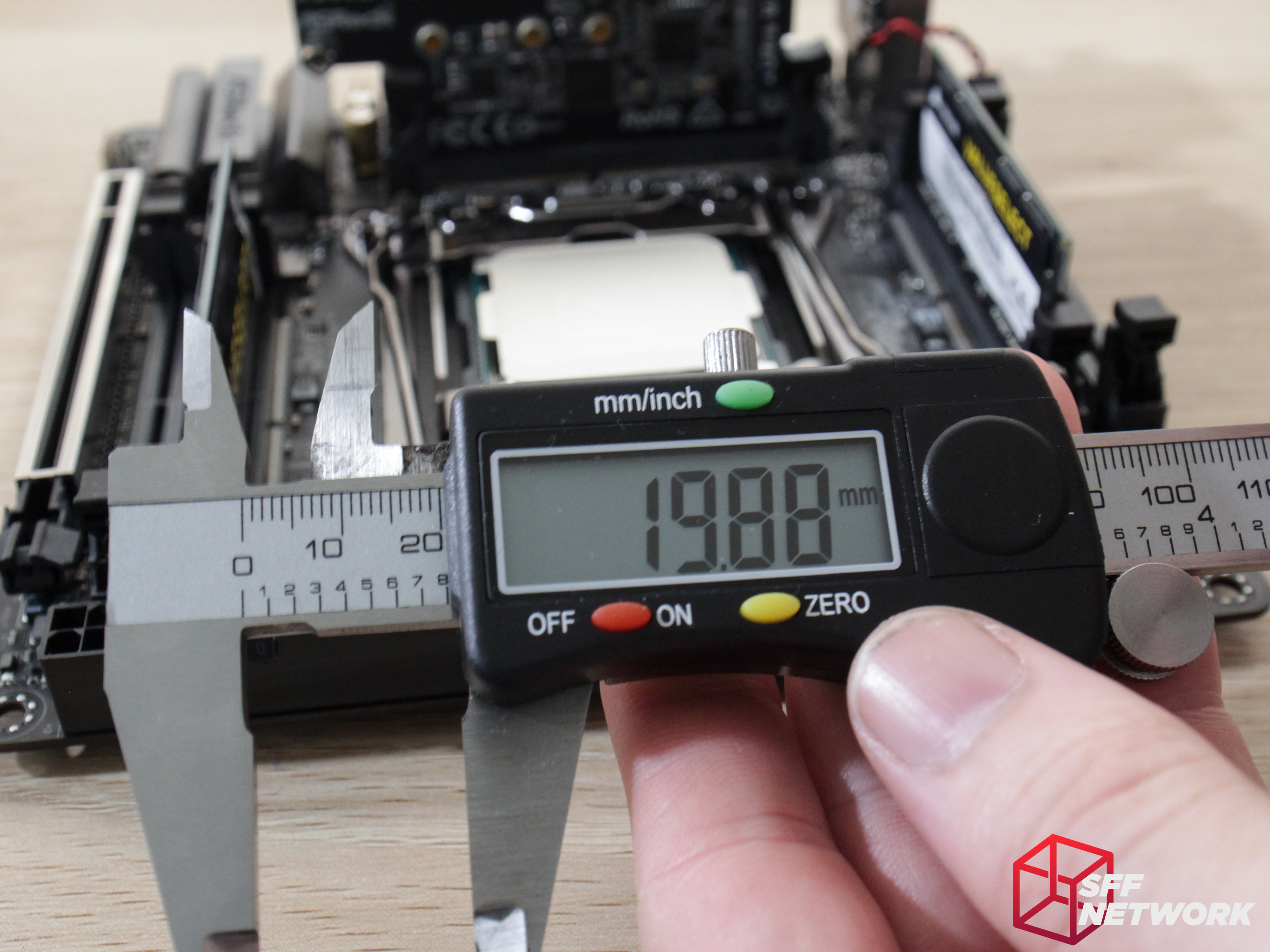
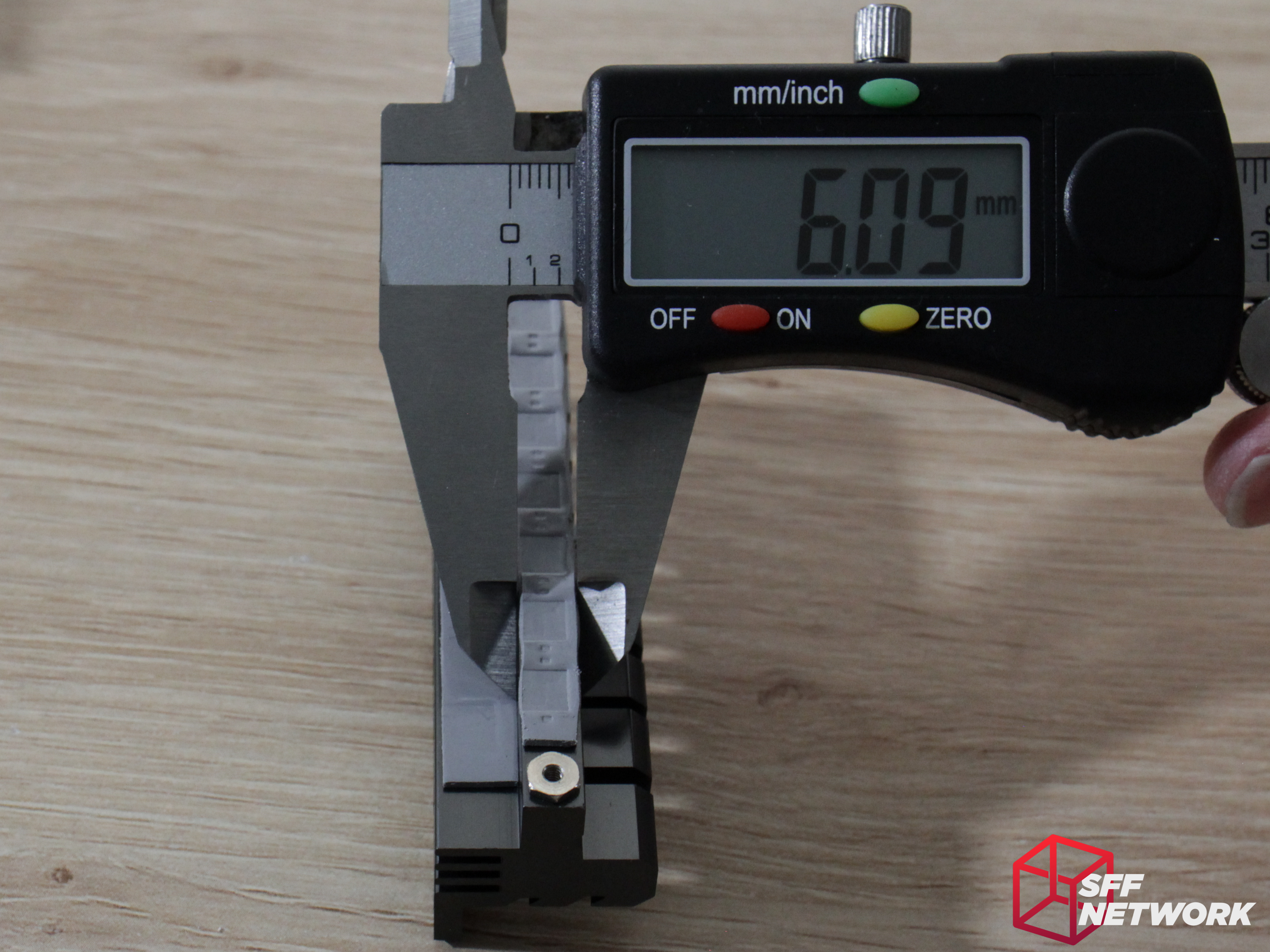
From the board, the main part of the heatsink is 19.9mm tall.

The daughterboard mounting tabs increase the total height to 27.7mm, however.

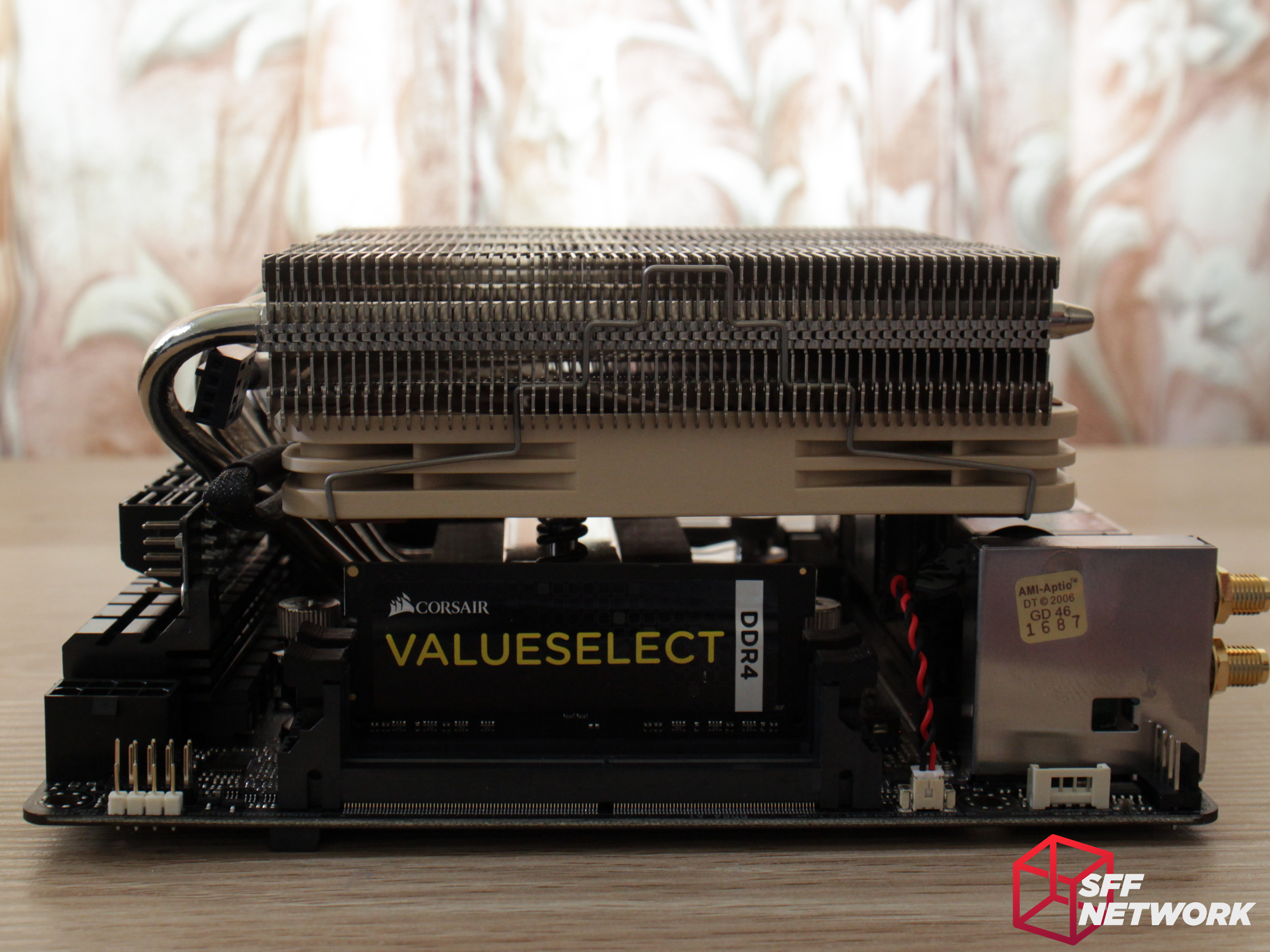
With RAM installed, the boxing in of the CPU socket area is obvious, and cooler selection will be critical.
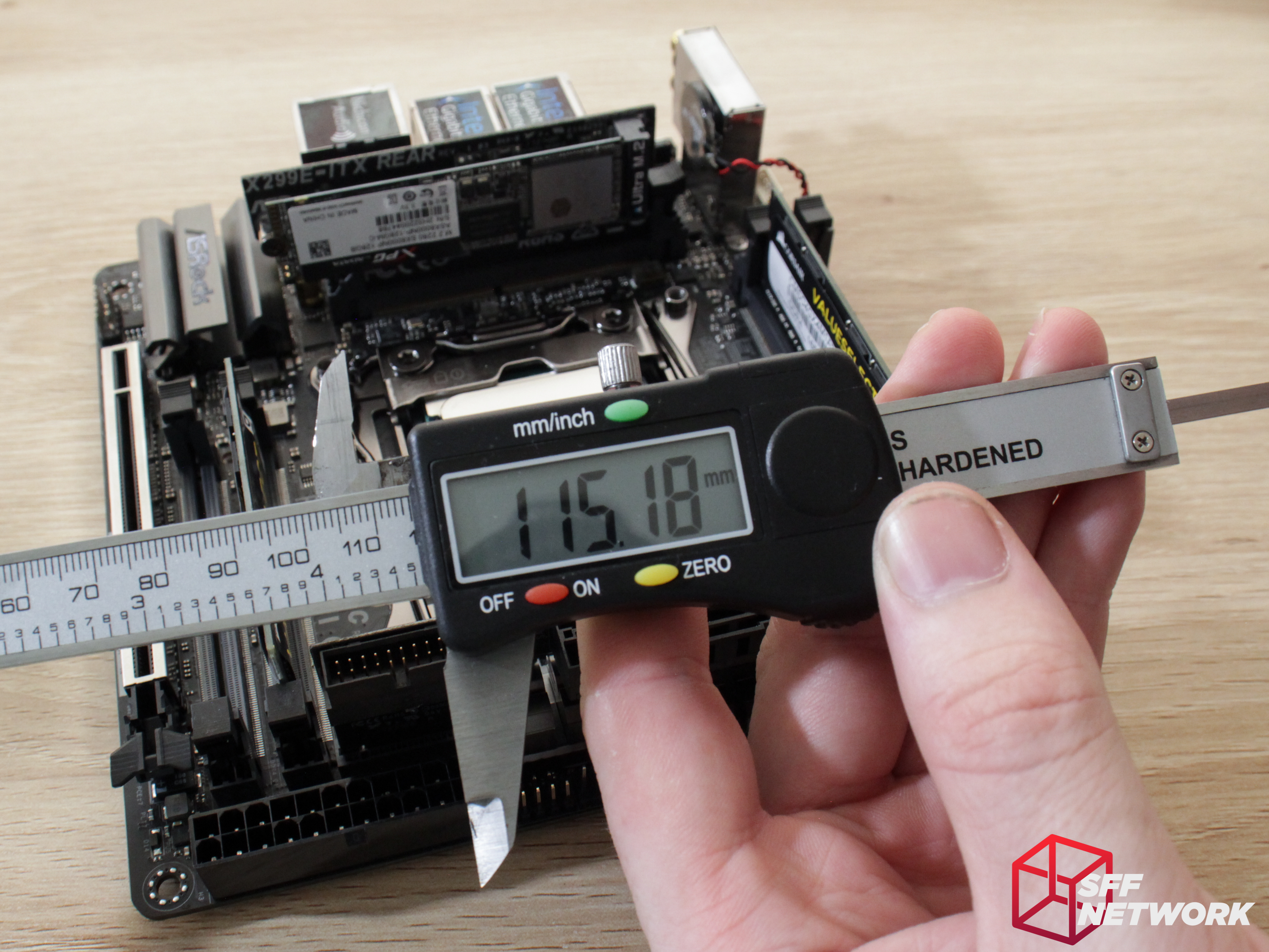
From RAM slot to RAM slot, there is 115mm of room, and;
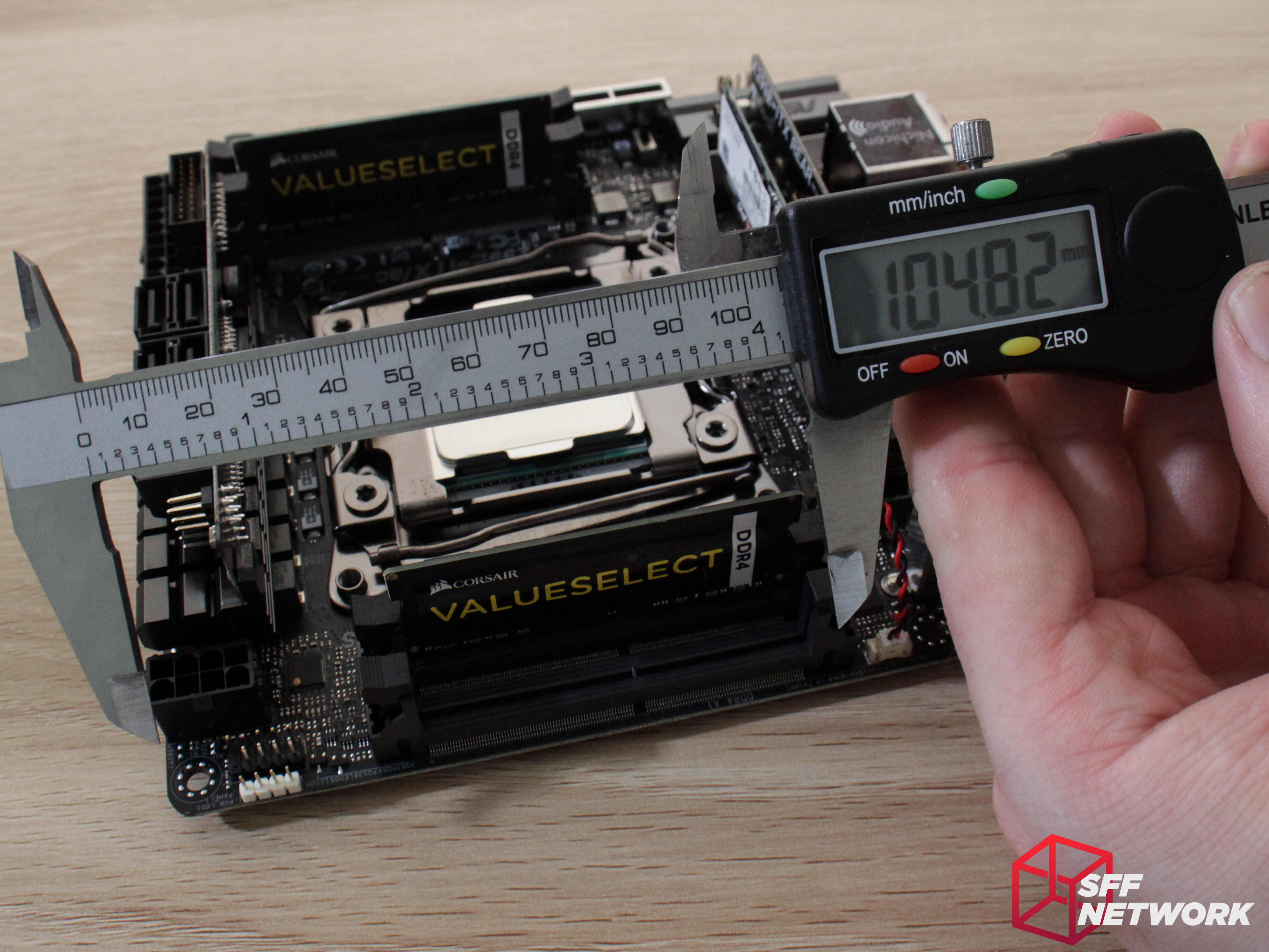
From daughterboard to daughterboard, I measured 104.8mm. These two measurements are your CPU cooler limitations up to the heights of these components.
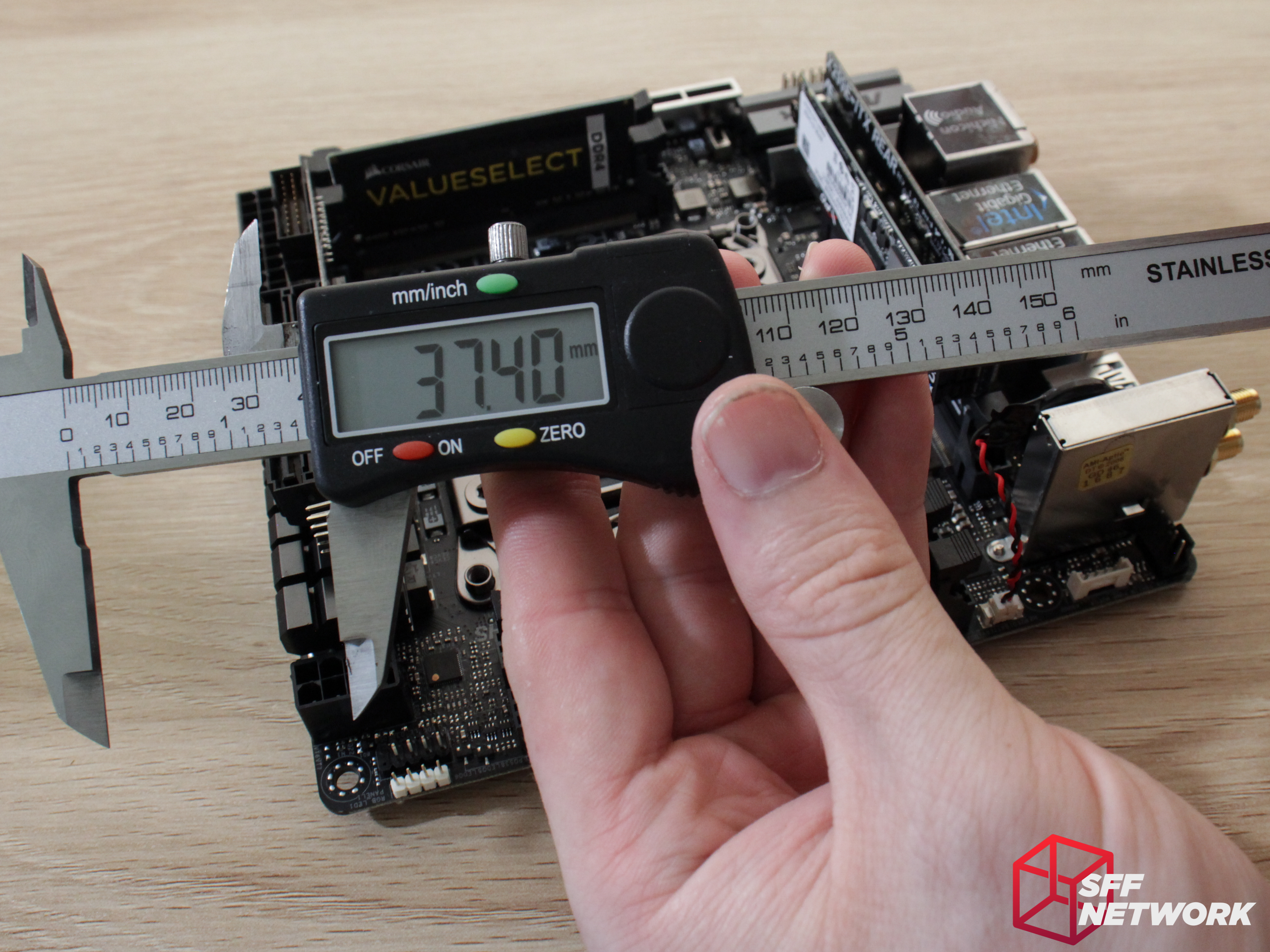
Installed, the rear daughterboard is 37.4mm high.
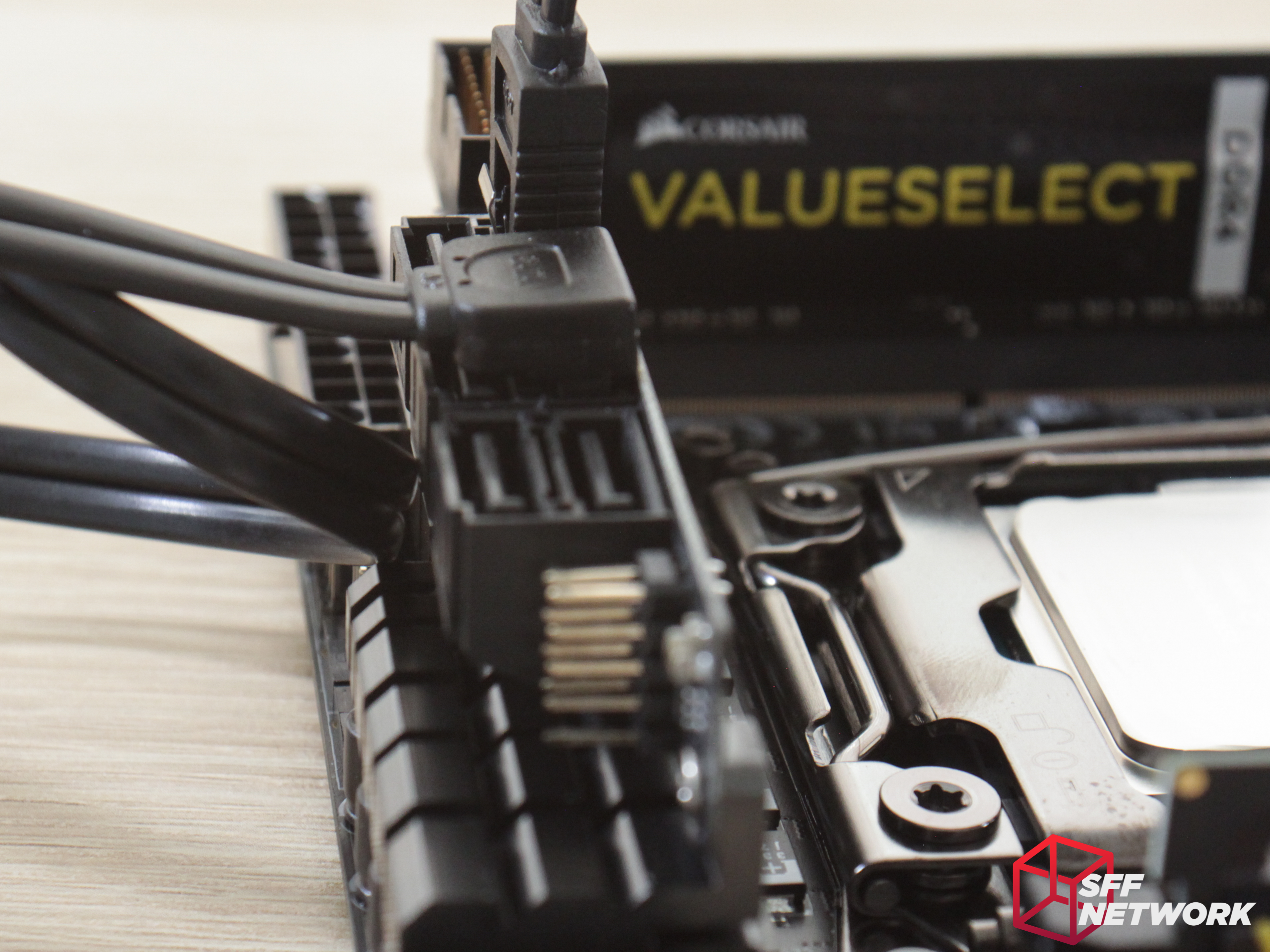
Adding SATA cables will dramatically increase the height of the front daughterboard!
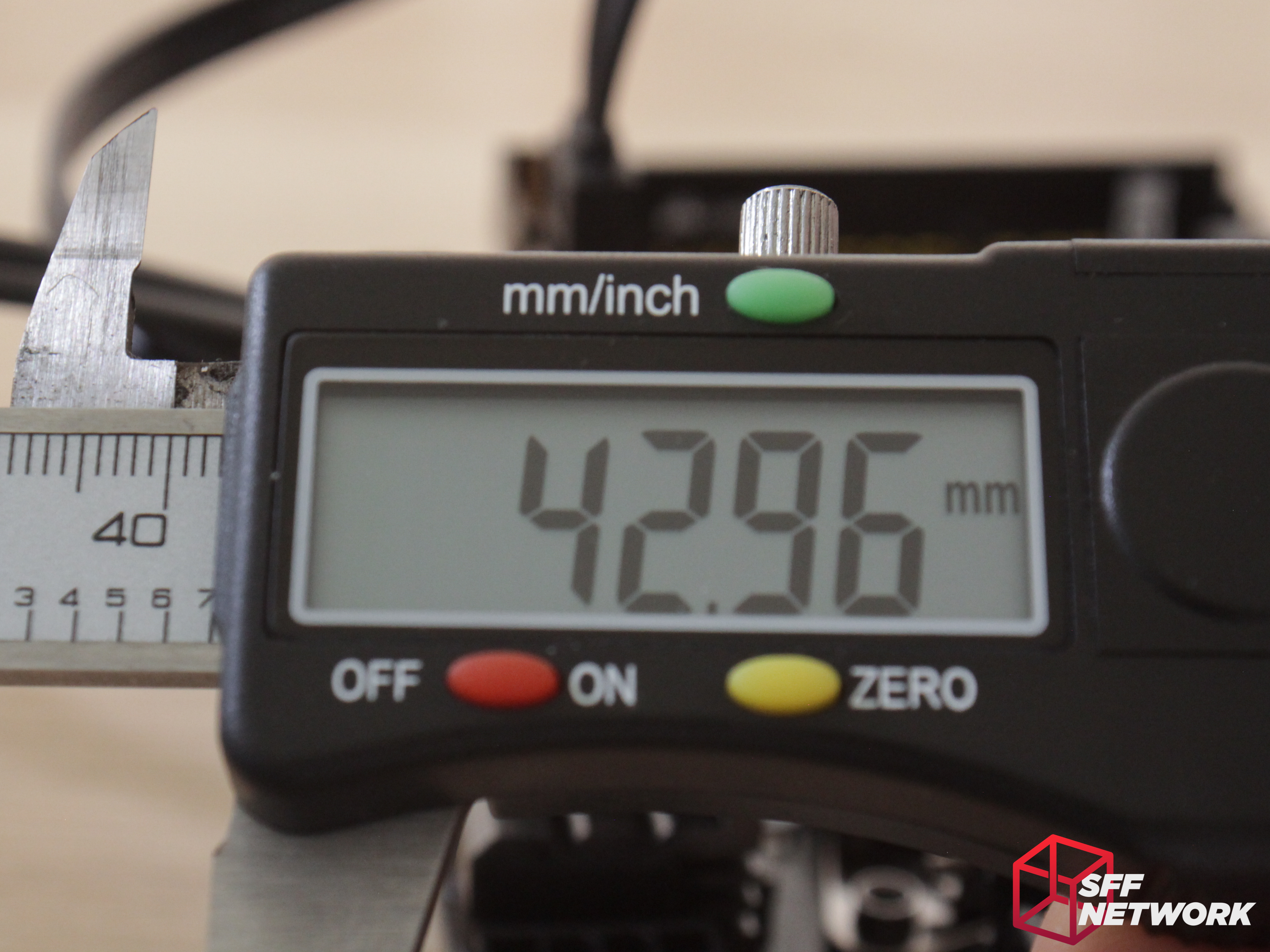
A right angled SATA cable will lead to a 43mm high airflow obstruction.
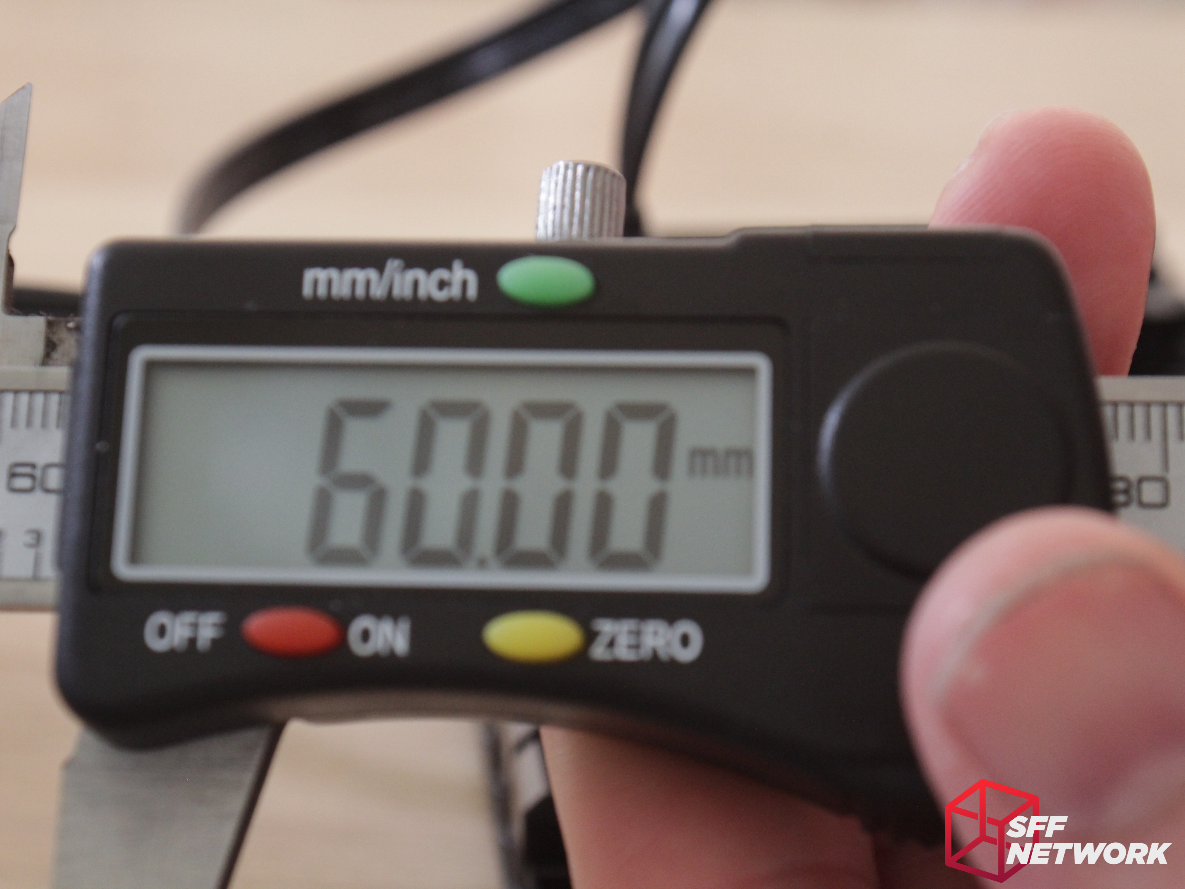
And a regular SATA cable, as included with the board, makes for a 60mm high combination.

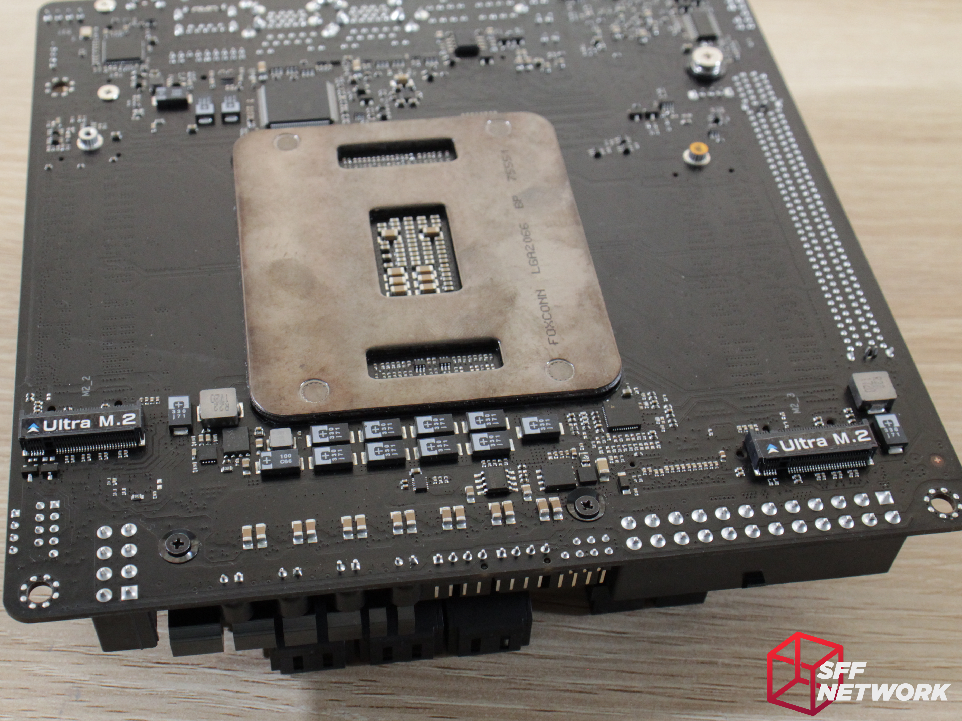
Two, yes TWO more M.2 slots are on the bottom of the board. the LGA2066 backplate takes up a considerable amount of real estate on this side of the board, much like the socket does on the other side.

This is the underside of the chipset mounting area, showing the screws used to mount the heatsink. To the top is a Nuvoton N76E885AT28, a MCU.

Two more chips. Installed between the two WiFi mounting screws is an ASMedia ASM1142 USB3.0 controller. To the top right is a Nuvoton IO controller – namely the NCT6791D.
LGA2066 CPUs need a large amount of VRM support, with the supported CPUs between the 140 and 165w(!) mark. There is a bank of componentry on the underside of the board to support the topside VRM circuitry!
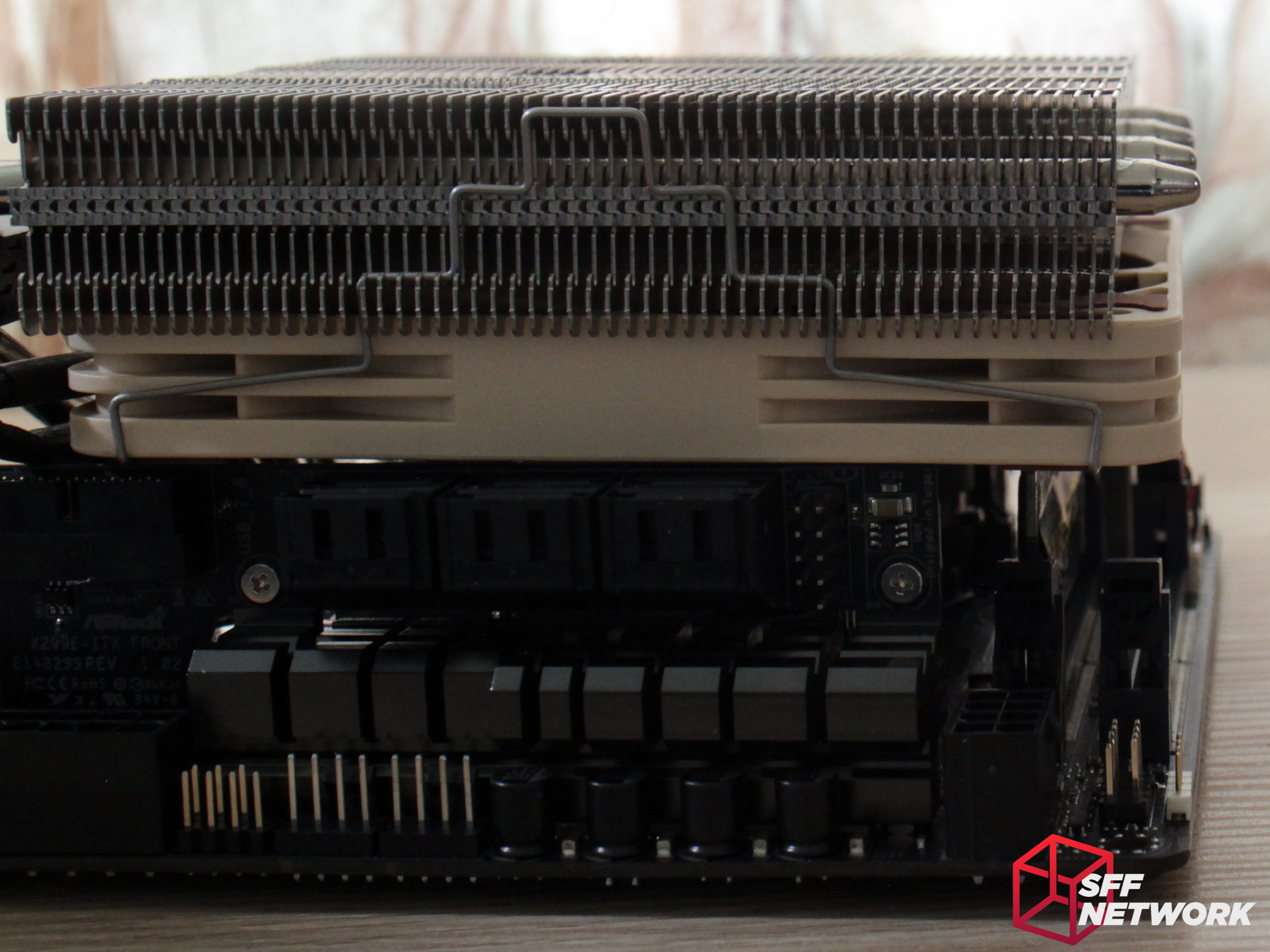
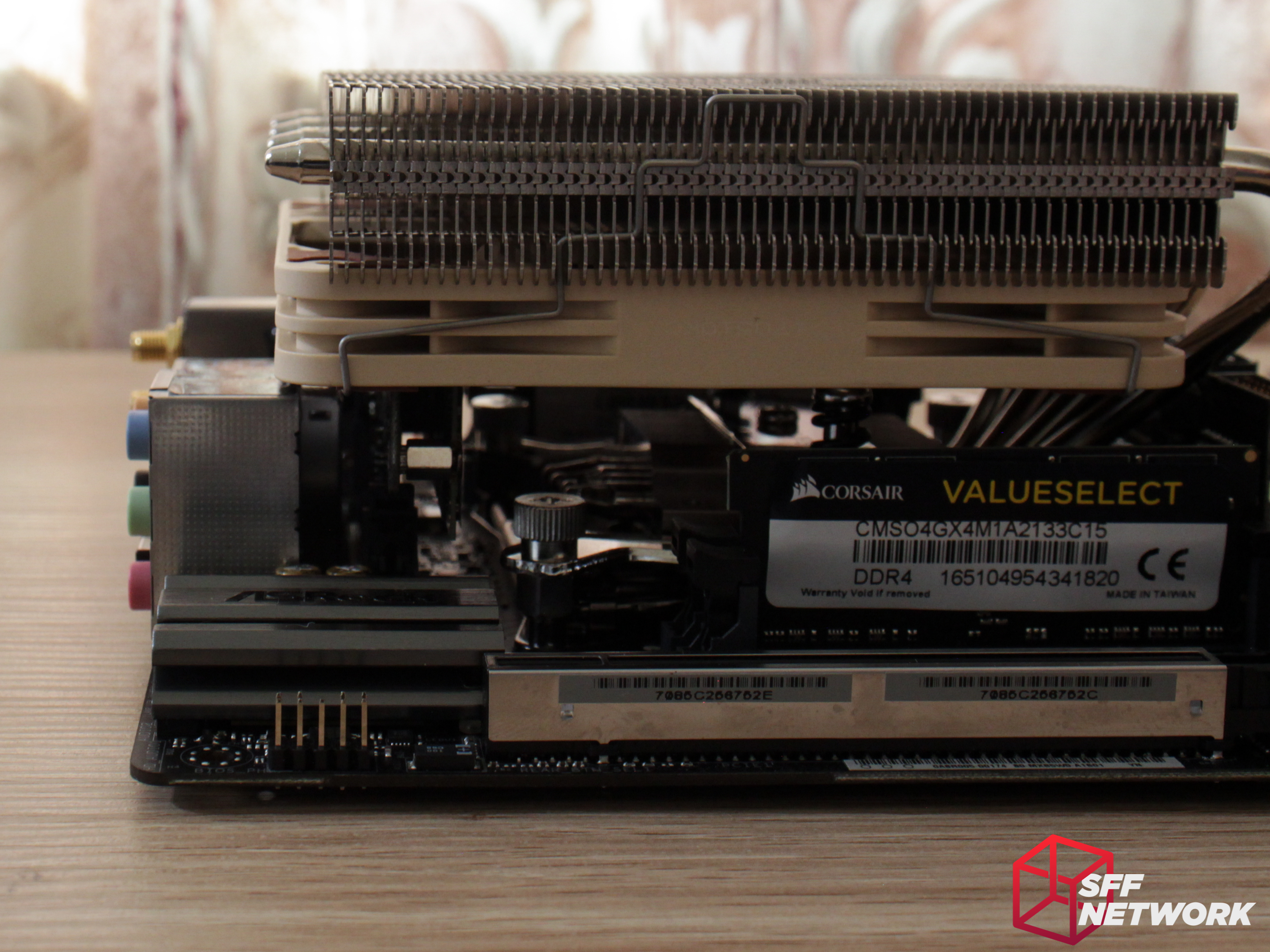
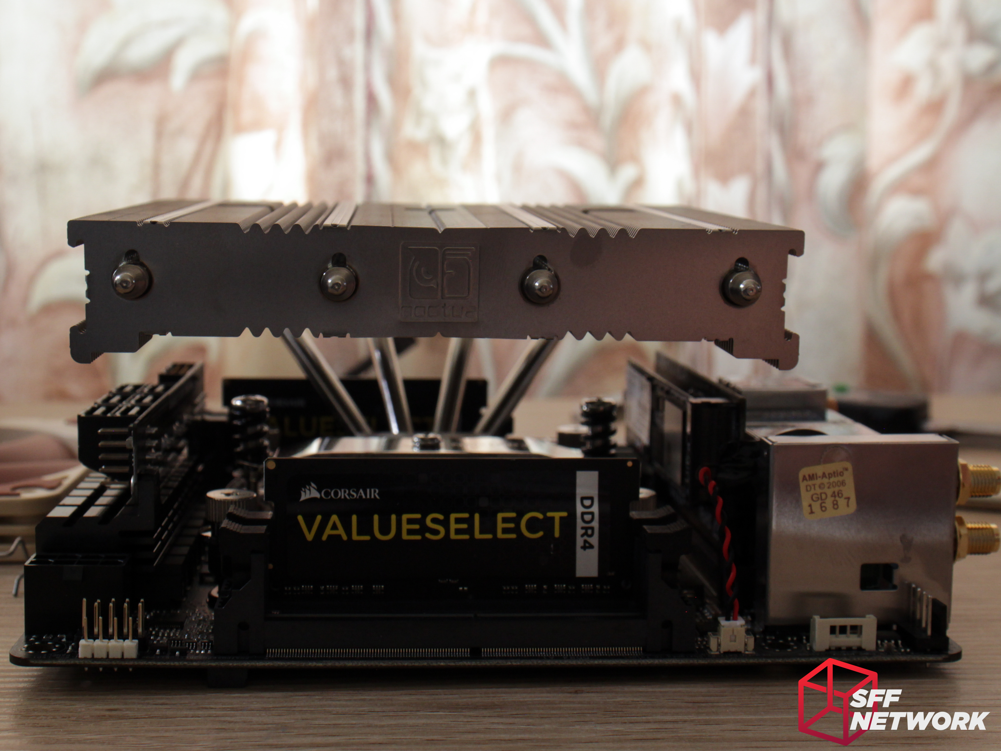
To test cooler compatibility, we used the newly released Noctua NH-L12s, courtesy of Noctua! (review coming soon). The cooler has replaced the bottom 92mm fan with a slim 120mm unit, enabling better cooling in lower profile configurations. Alas, in this config, the daughterboards are a couple of millimetres too tall. Dang! The cooler sits nicely in every other regard though, not blocking RAM, ports or hanging over the edge of the board.
If only!
Not even close to the PCIe slot, which is great for those cards with backplates.
Even taller RAM modules would work with this cooler.
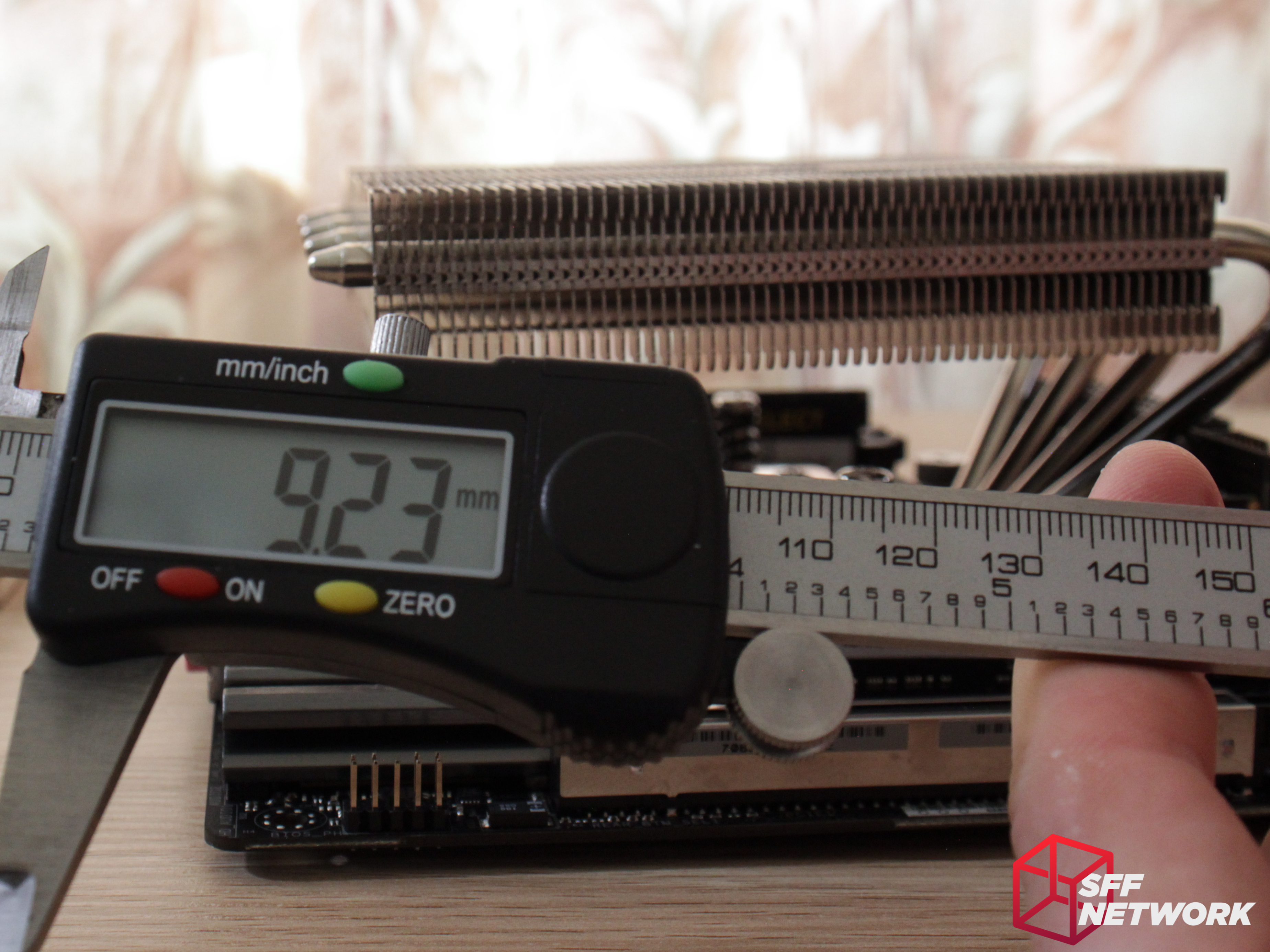
Removing the slim fan, we find that the cooler sits 9.23mm above the rear daughterboard. No wonder the slim fan didn’t fit! Mounting the fan to the top of the cooler is an easy solution, if you have the space. Remember, the LGA2066 CPUs are power hungry beasts, with our i7-7800X weighing in at 140W!
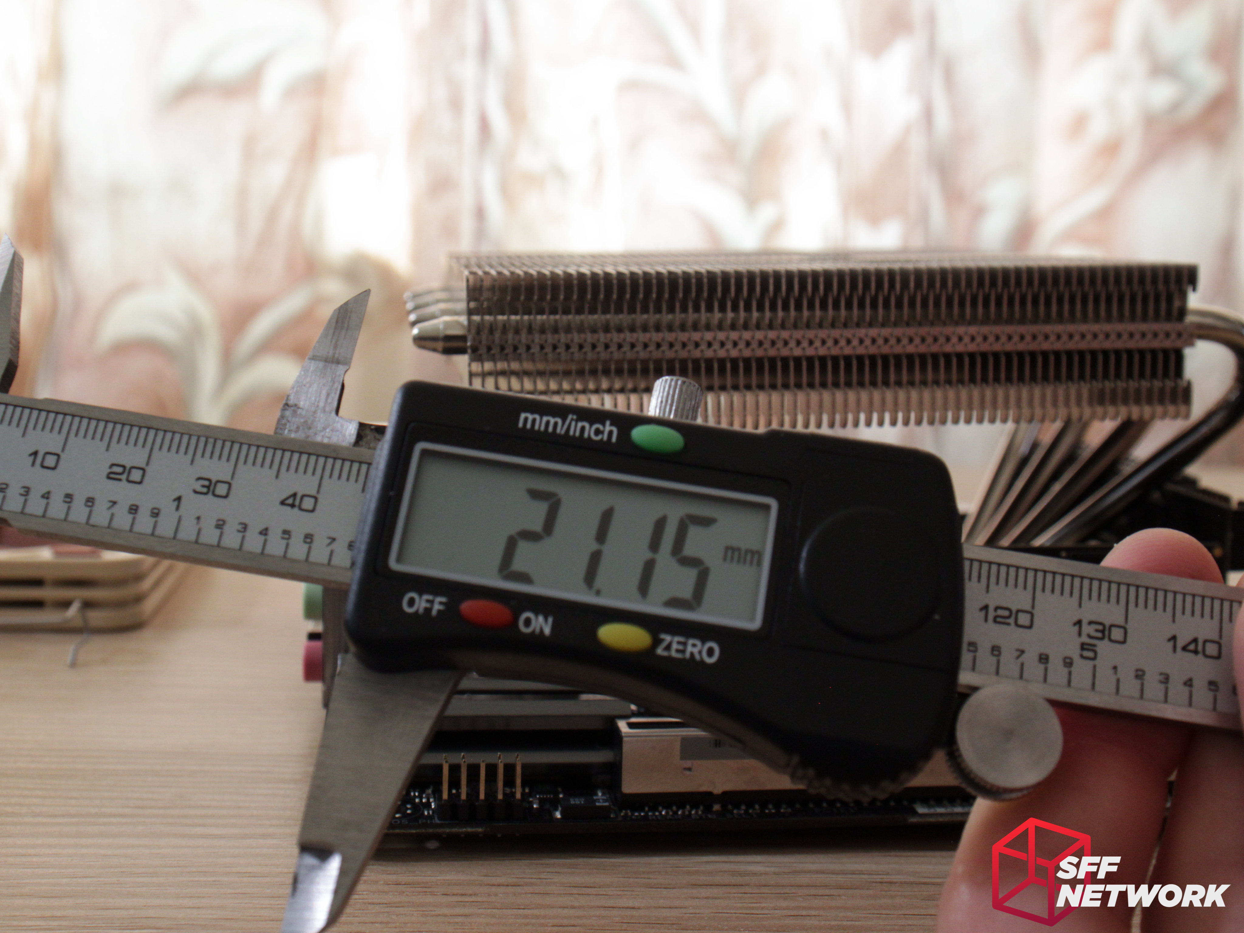
21.15mm between the cooler and the RAM. Not bad.
As you can see, with the bottom fan gone, there is a tonne of room. Noctua, care to release a 9mm 120mm fan?
The BIOS
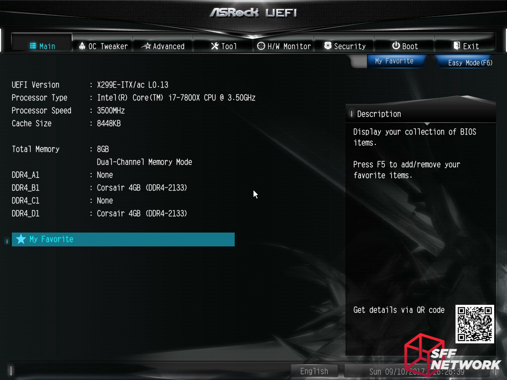
Like the packaging, the BIOS screens are simple and subtle. Once again, no flashiness, gamer branding or the like, just formal and usable. On this first page, the CPU, board version, and RAM loadout is shown.
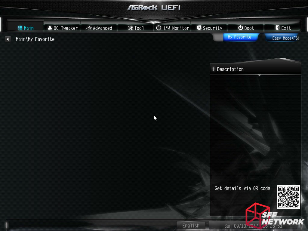
“My favourite” enables you to set favourite menu items using the F5 key – handy for overclockers!
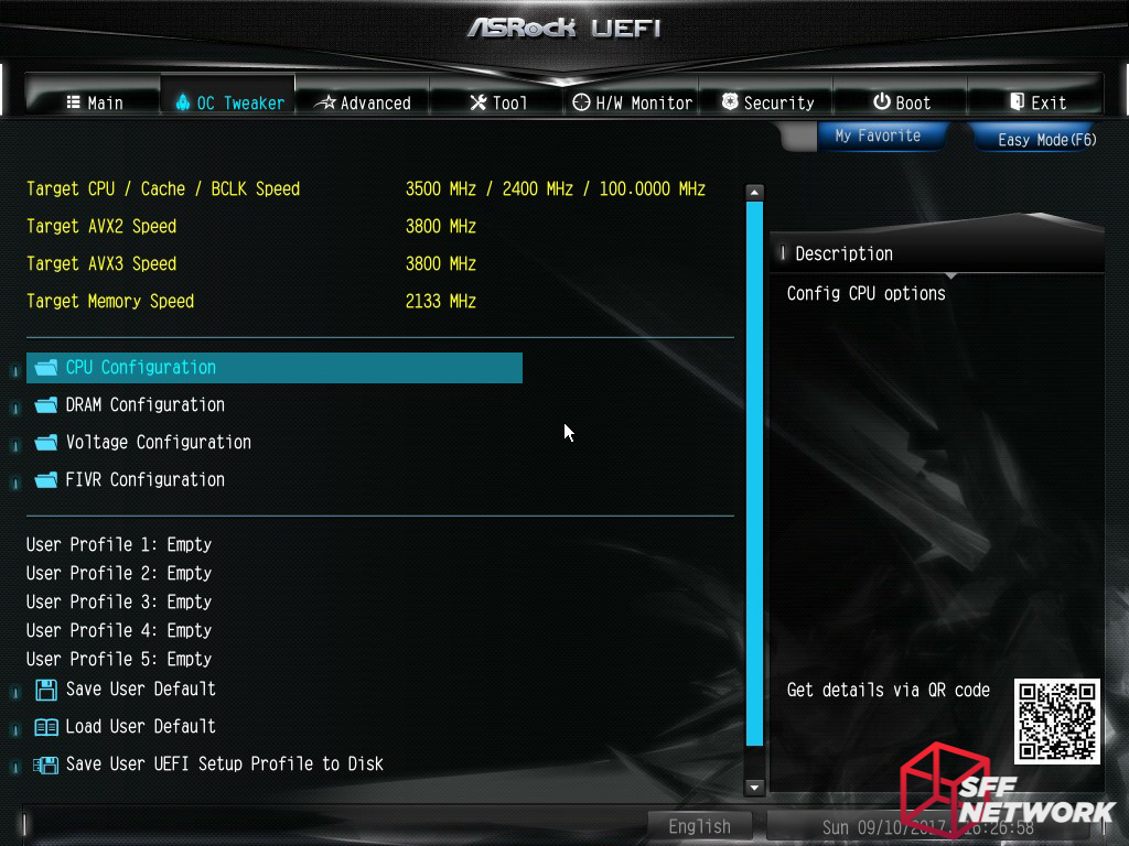
Under the OC Tweaker menu, we have access to all the fun functions, tweaking system performance to your personal satisfaction.. within the bounds of the silicon lottery of course!
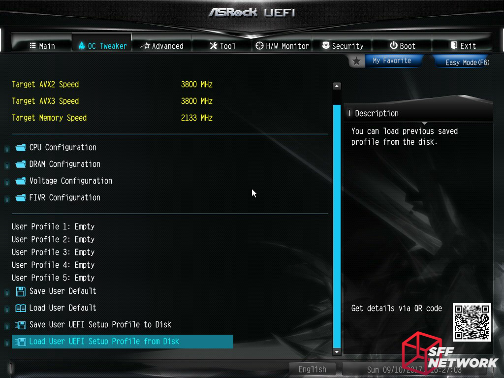
The menu allows you to save up to 5 configurations for ease of application later – handy if you have various configurations that are stable under different loads. However, I am a fan of having one all-purpose config, so this saving wouldn’t be useful for me.

Under the CPU submenu, we can start to tweak the system to our liking. CPU ratio and BCLK are modifiable from here – although, with the recent concerns over X299 platform VRM stability, your results may vary. While settings like CPU Ratio and BCLK may be self explanatory, Mesh and Flex aren’t as well known. Flex Ratio is the minimum CPU multiplier the system will use. Mesh is the CPU internal bus (Like AMD’s Infinity Fabric).
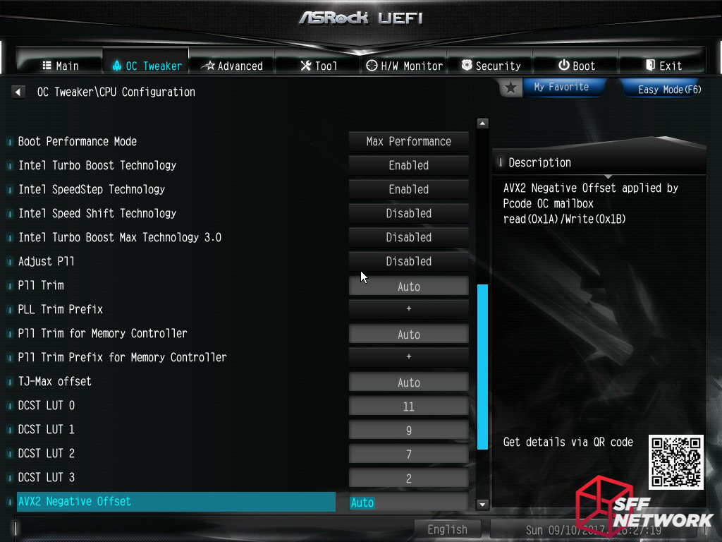
More options are hiding further down the page, from boost modes, PLL configuration, temperature adjustment and a couple of options I’m not familiar with!

And more options. The power limits limit how far and long turbo boost will go for – if you are confident in your cooling and power supply, you can increase these.
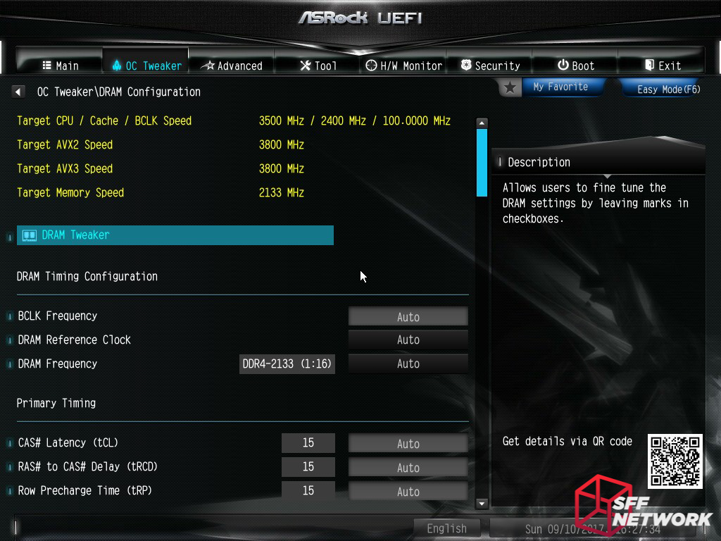
Now for the memory timings. Once again, this stuff is dark magic, and I only understand the basics!
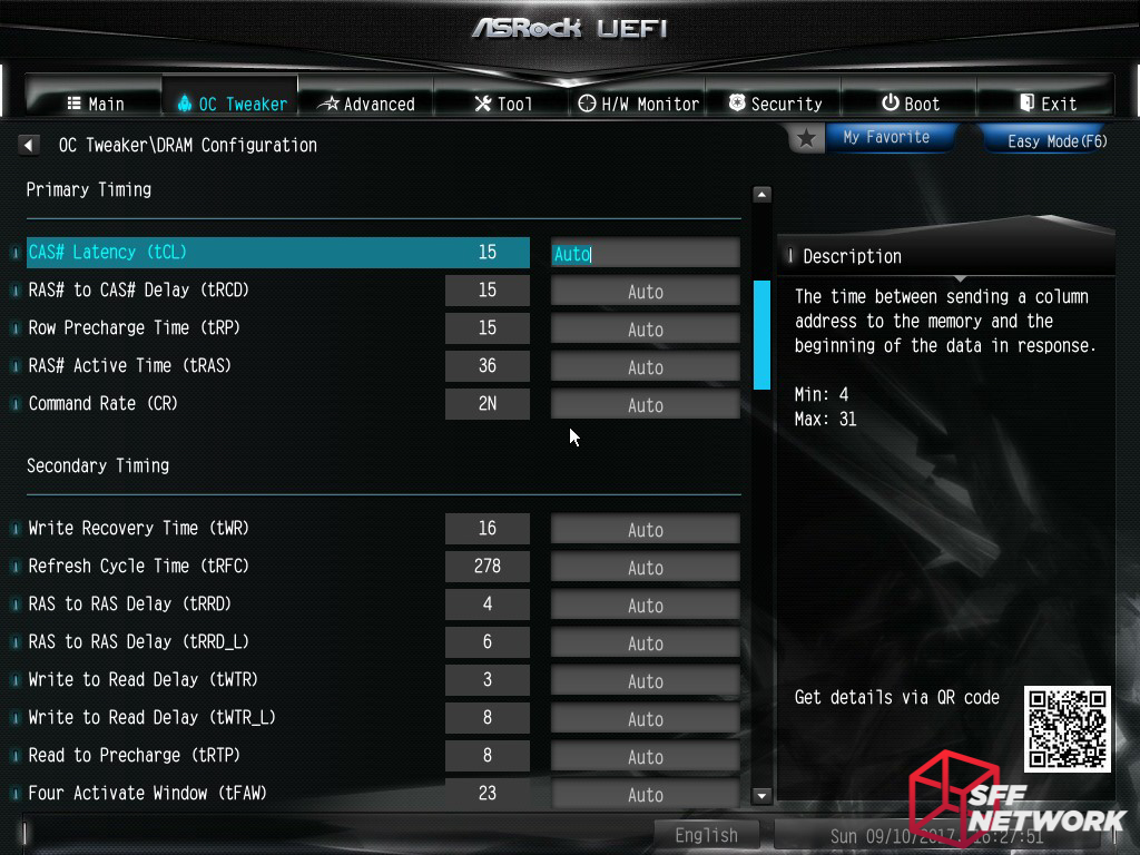
More…
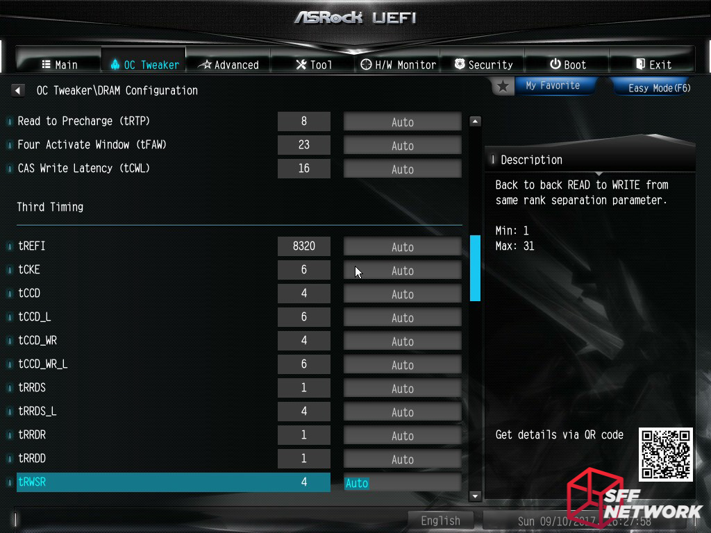
Much more…

But wait, there’s more…
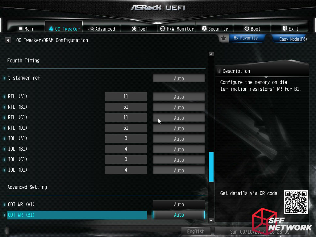
More!
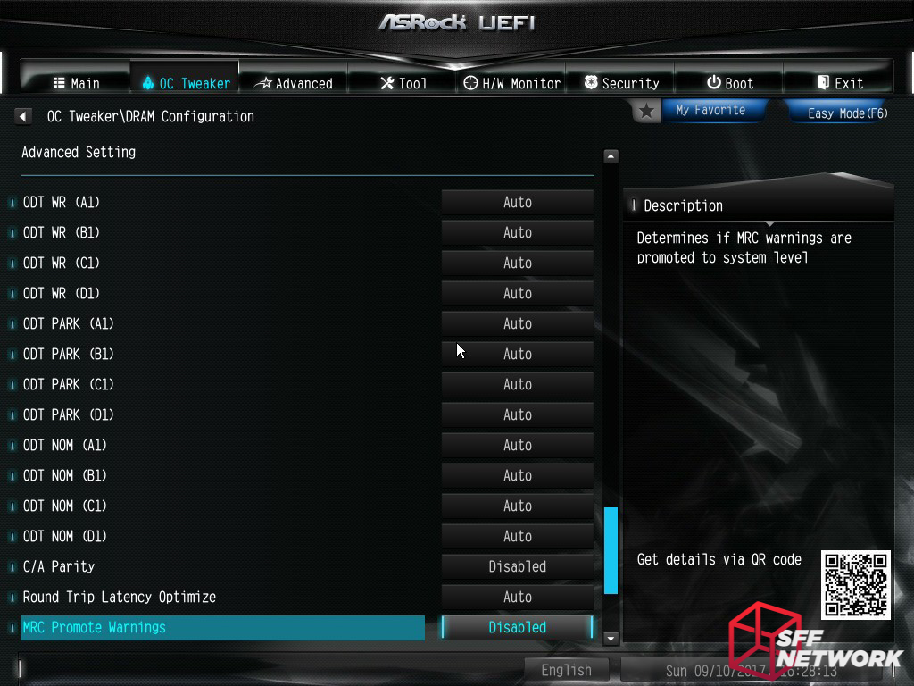
Moar!
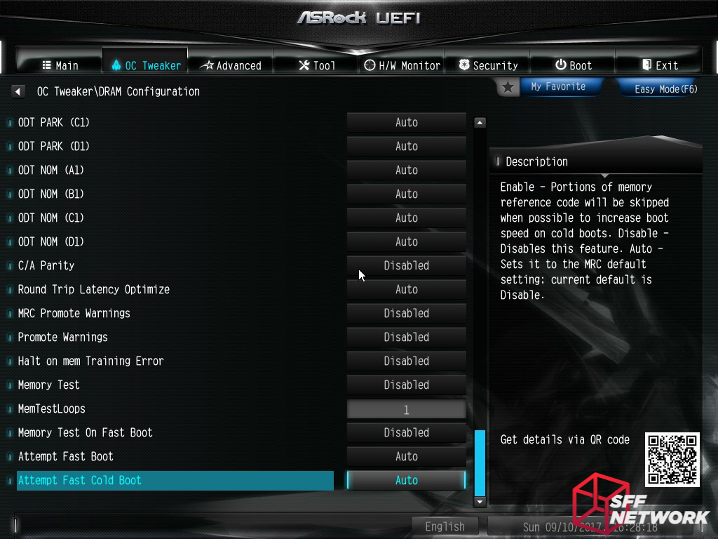
More.
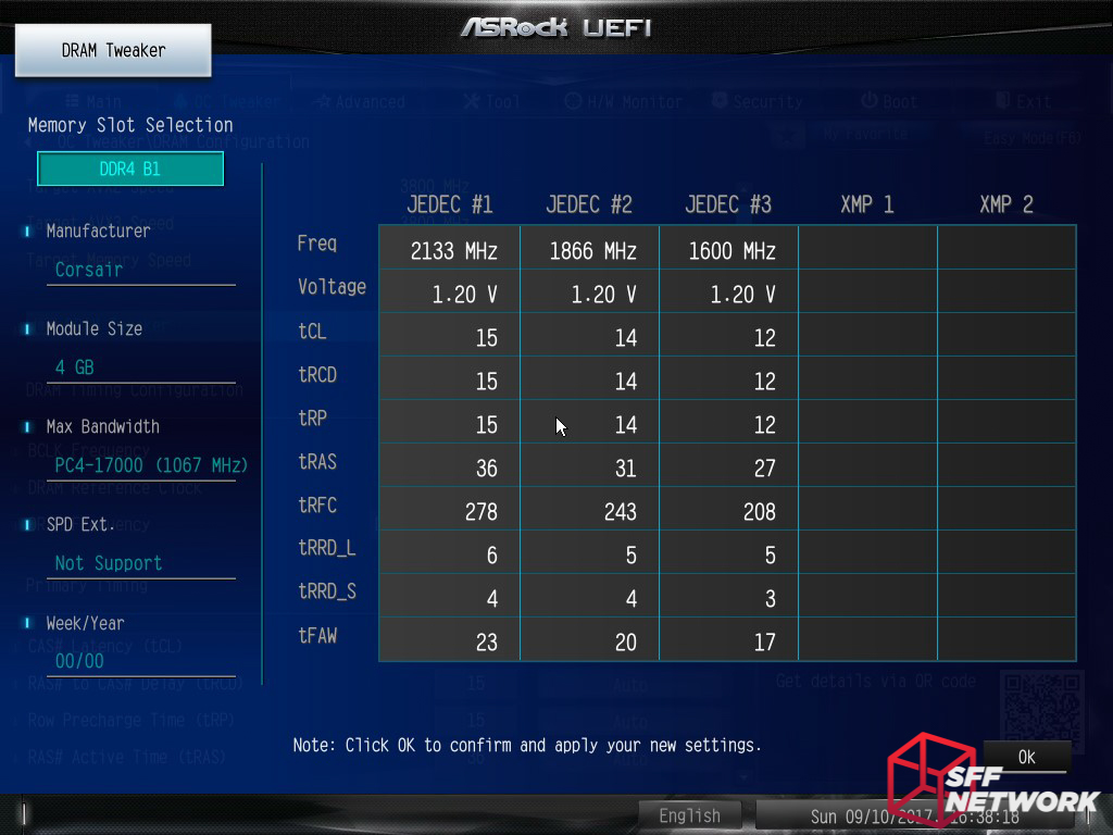
A simpler way to overclock or tweak your RAM settings is via the DRAM Tweaker menu, which gives you access to the commonly adjusted settings, as well as shows you the JEDEC settings that are stored in your RAM’s controller chip.

Voltages Submenu, here lies dragons. This menu makes or breaks an overclock, or breaks your board, depending on your skill level!

FIVR – Fully Integrated Voltage Regulators – a smarter voltage regulator solution in essence. Here you can adjust various settings relating to that.
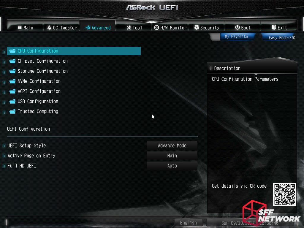
The advanced menu hides the more… advanced… options for your system.
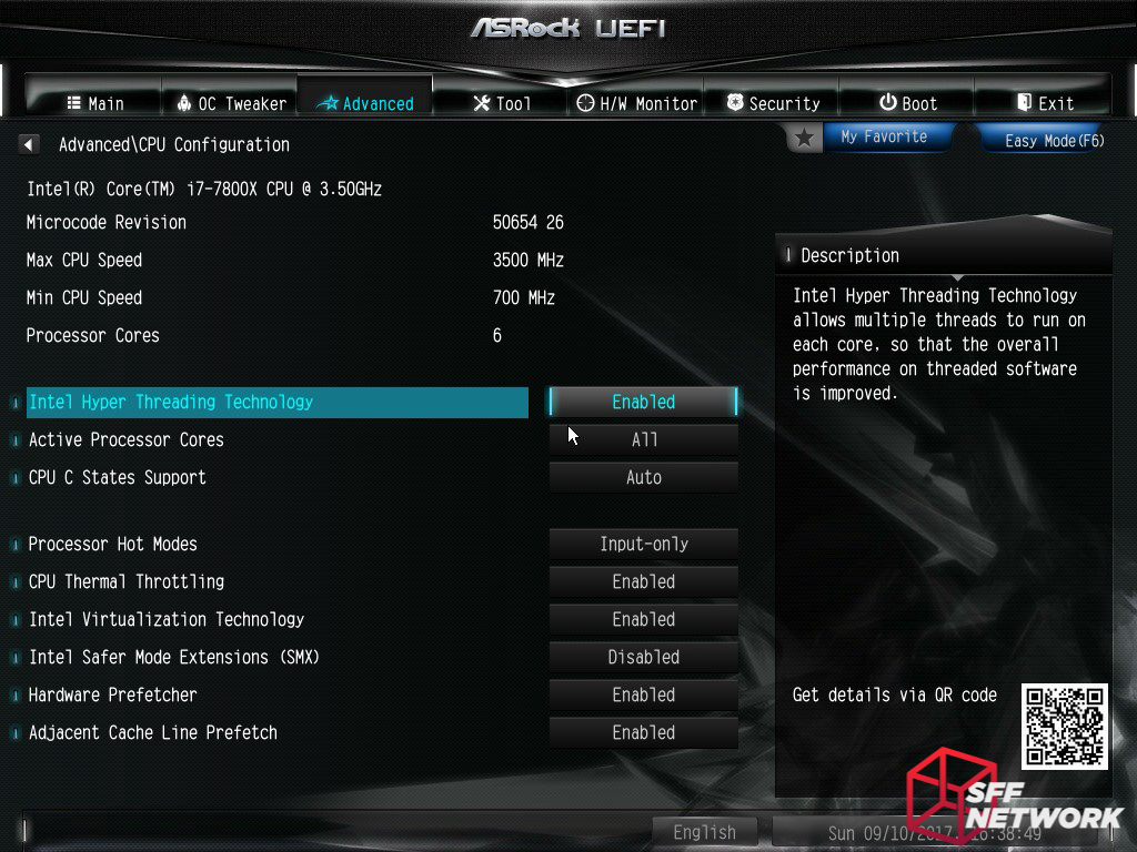
Some of the more advanced features of your processor can be modified here – Hyper Threading, C States, thermal throttling, virtualisation and the like.
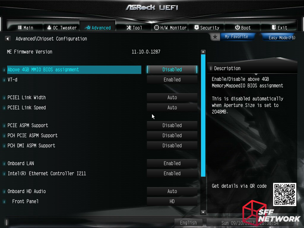
Herein lies the secret to bifurcation, the PCIe1 Link Width – you need to set this to enable bifurcation with an appropriate riser. Also hiding in here is the ability to enable and disable wired LAN, ASPM and Audio.

Oh, and you can disable WiFi from here, and set your system to do different things when AC power is lost/regained.
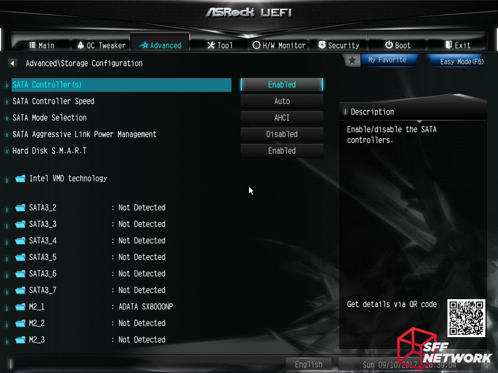
Storage options shows what drives you have connected, as well as the ability to change modes, speeds and power management.

Intel Volume Management Device is a NVMe drive hotswap technology, mostly aimed at datacentre use.

NVMe configuration is a pretty minimal menu, it just gives information on devices on the NVMe bus.
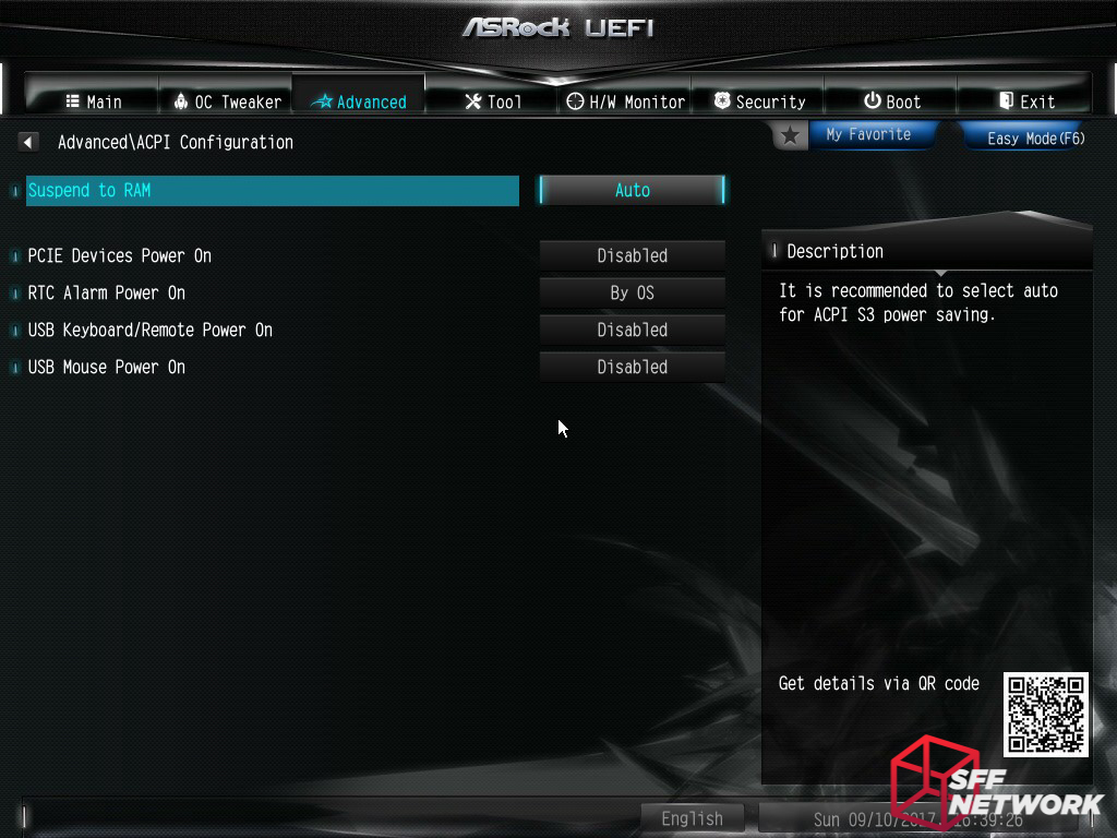
ACPI settings – handy for enabling peripherals and devices to power on your compute.
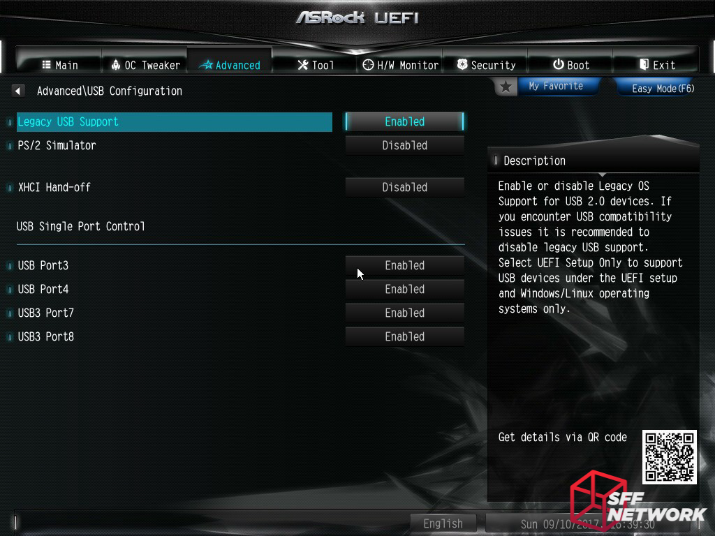
USB configuration is in this submenu.
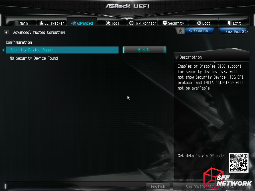
Trusted Computing Module configuration options are in the Trusted Computing menu. On the Intel ecosystem, the TCPM is still on a discrete module, unlike on the AMD Ryzen platform, where there is a portion of the device integrated into the processor.
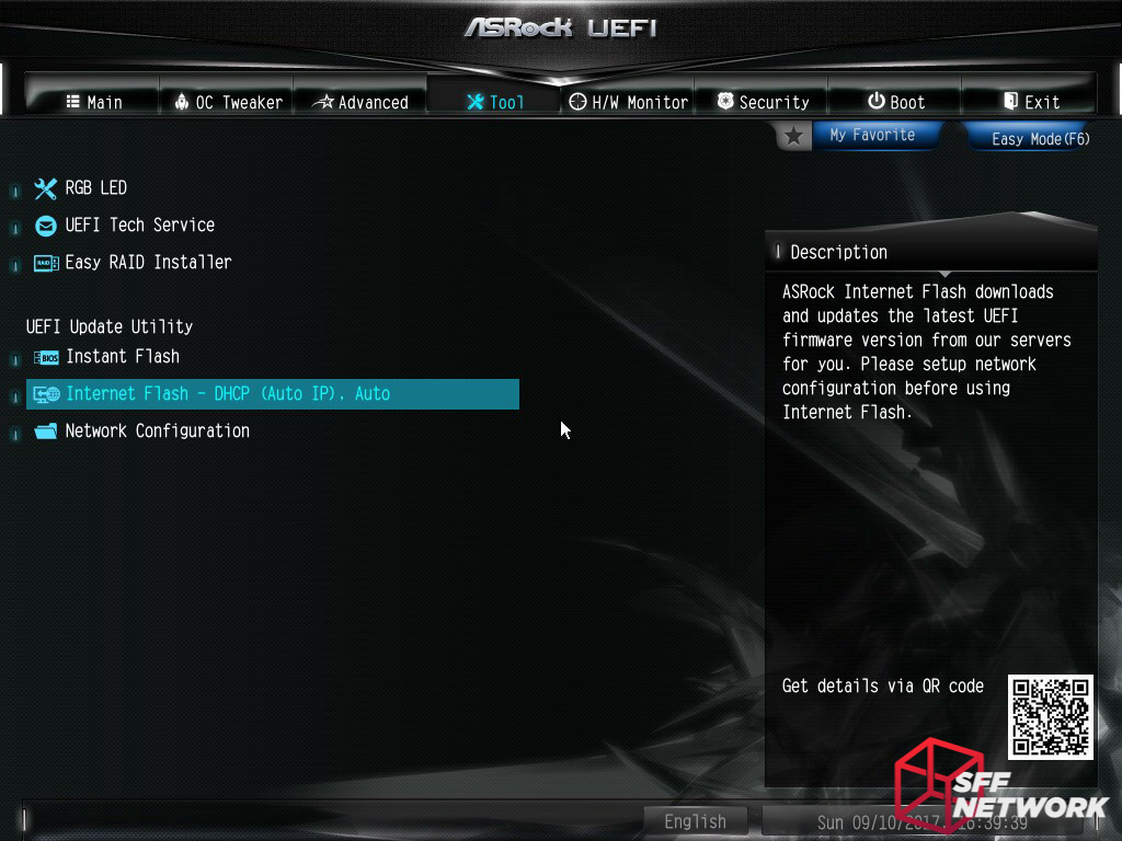
Tools!
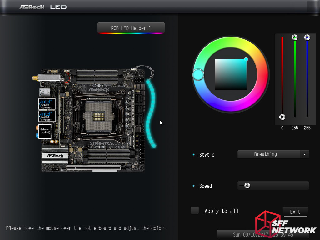
Mirroring the utility in Windows, the RGB control menu is simple and easy to use. The image shows the actual motherboard model! (unlike other motherboard RGB utilities I have tested!)
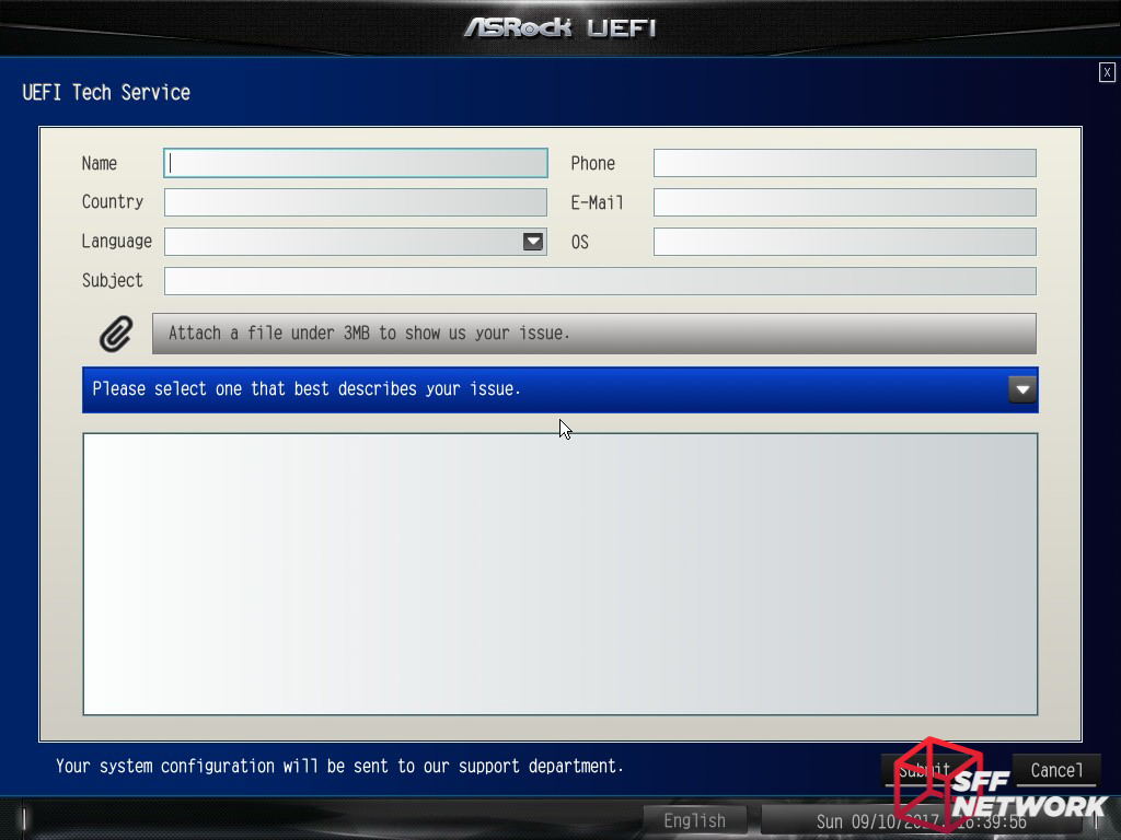
You can send a support request from within the UEFI environment – very useful if you just can’t get a system configuration to boot an operating system. The message sent to ASRock will include your system configuration, which will aid in support.
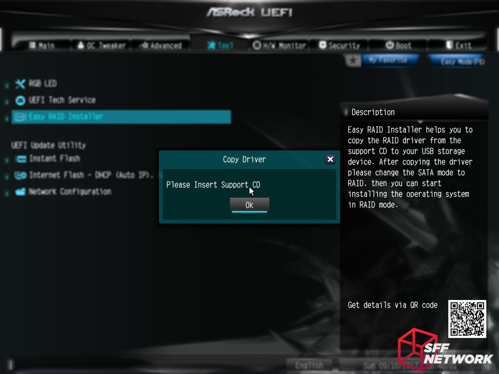
The Easy RAID Installer needs the Support CD to be inserted.. I don’t even own an optical drive anymore! I figure a USB stick version can be used though.
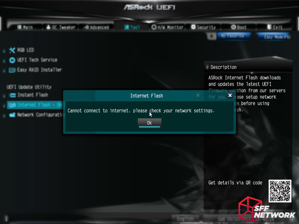
Woops, haven’t set up the network yet. I couldn’t get the board to connect to WiFi from within the UEFI environment, so a wired connection would be needed for this to work.
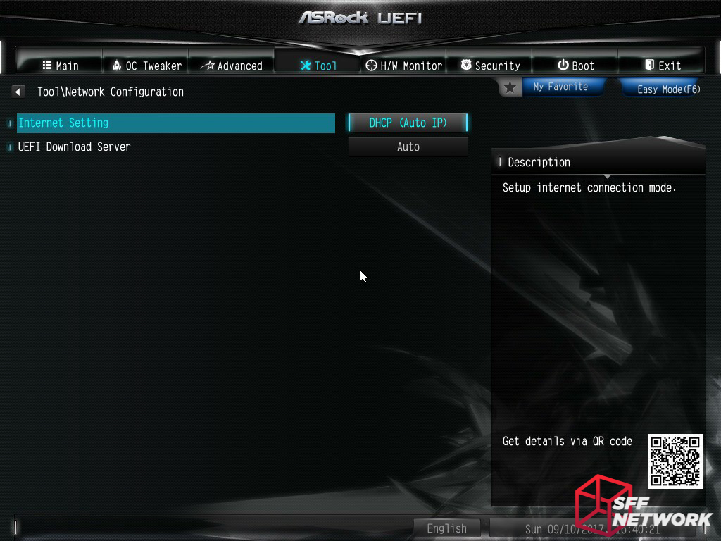
Network settings for the BIOS flashing tool.
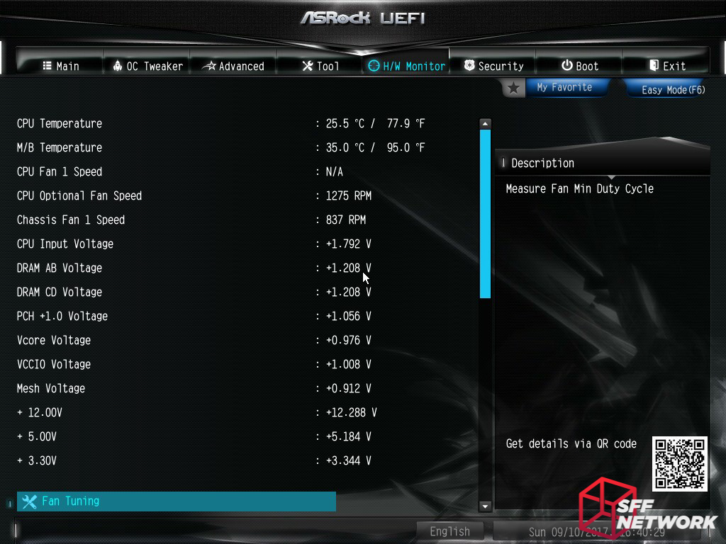
The usual hardware monitoring information is shown in this submenu.
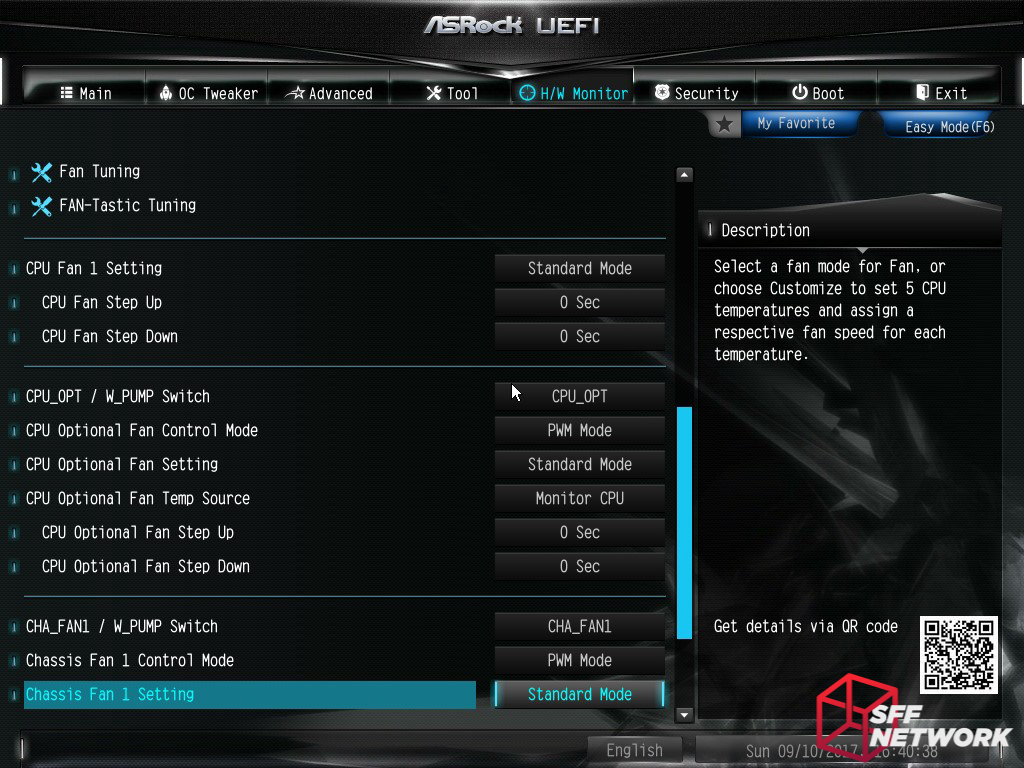
Scrolling down, we have access to some options – configuring the fans, the headers and the modes. The CPU_OPT and CHA_FAN1 headers can be configured to be used for a waterpump instead of a fan. These two headers also have the ability to be switched between watching the CPU or Motherboard temperature sensors from which to base their speed.
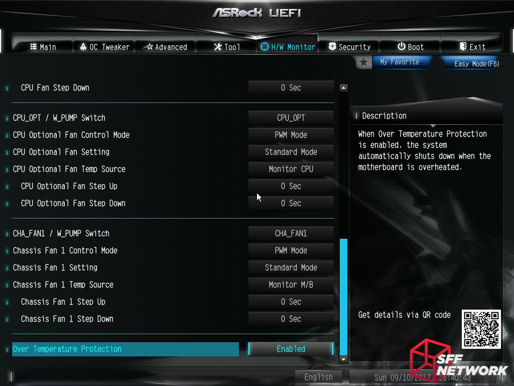
OTP, very important!
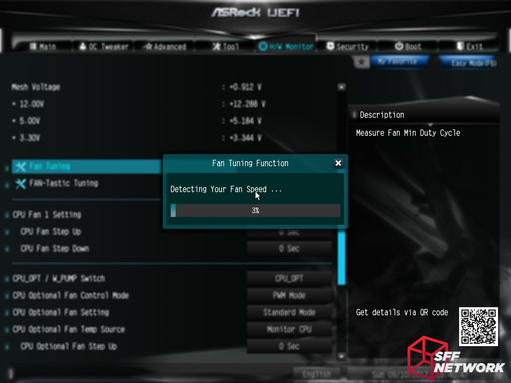
Fan Tuning will run all connected fans or pumps from 0 to 100% PWM duty cycle and ascertain the characteristics. As an example of this being useful, there’s no point tuning a fan profile to go down to, say, 20% PWM if the fan won’t even spin until 30%!
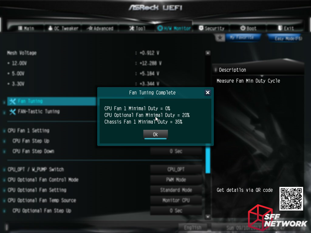
And results! Yeah, I put the CPU fan on the wrong header. Woops!
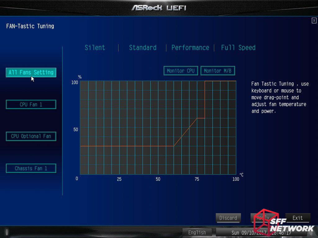
The Fan-Tastic (budumptish) Tuning Utility is a graphical app allowing tuning of fan curves.
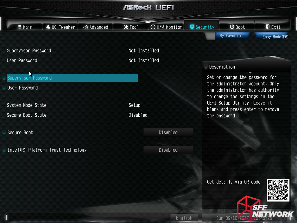
Nearing the end, we have security settings, so those pesky plebeians don’t have access to our settings!
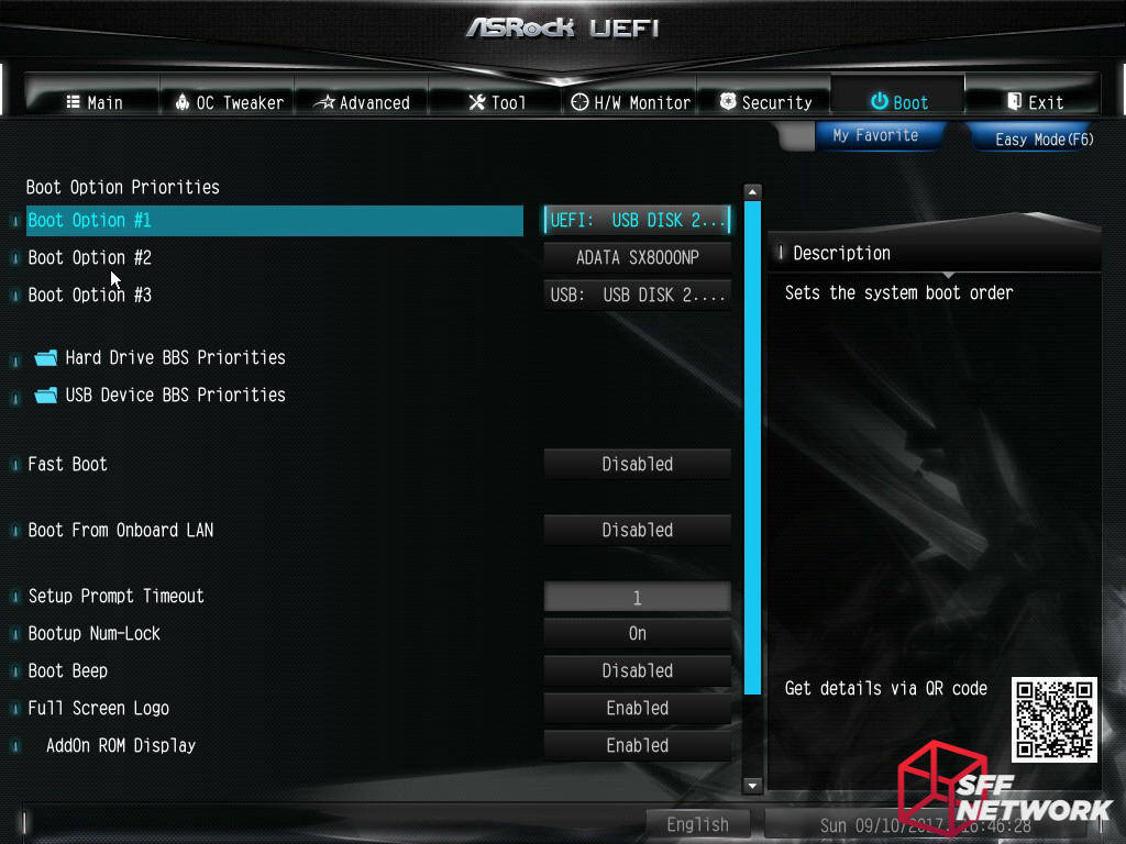
Picking a boot device is rather important..
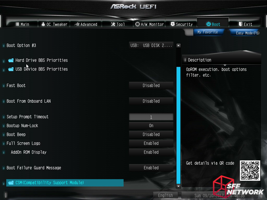
Fast Boot, beeps and displays are configurable.
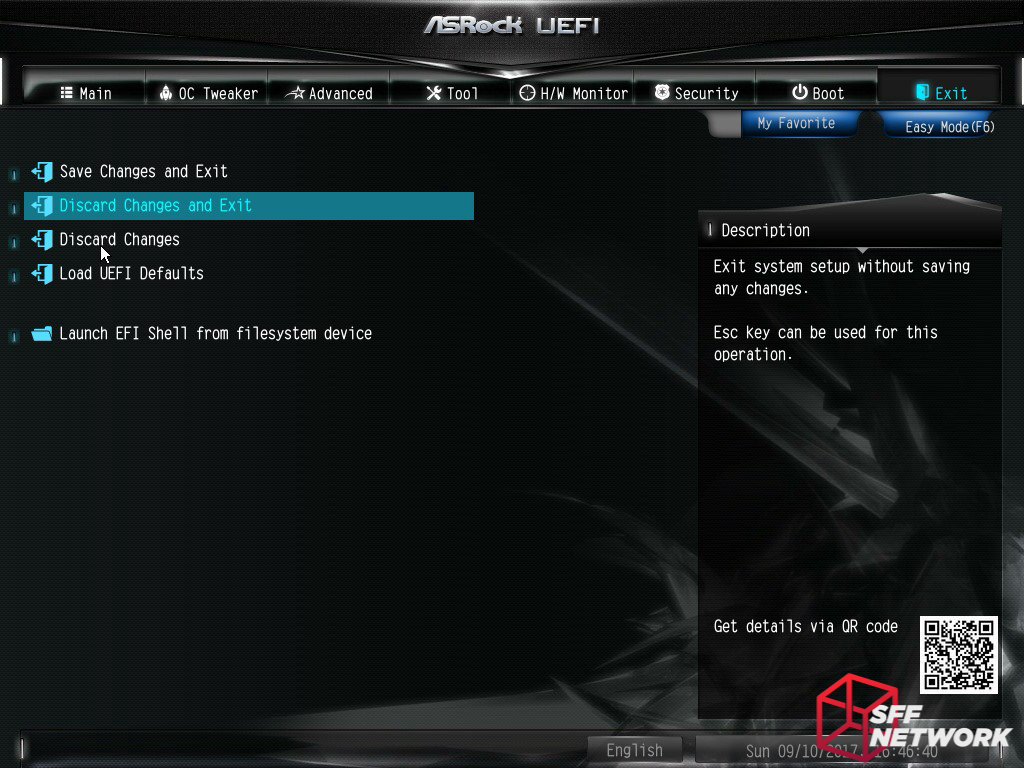
Run away! Save your settings on the way out though..
The Cooling
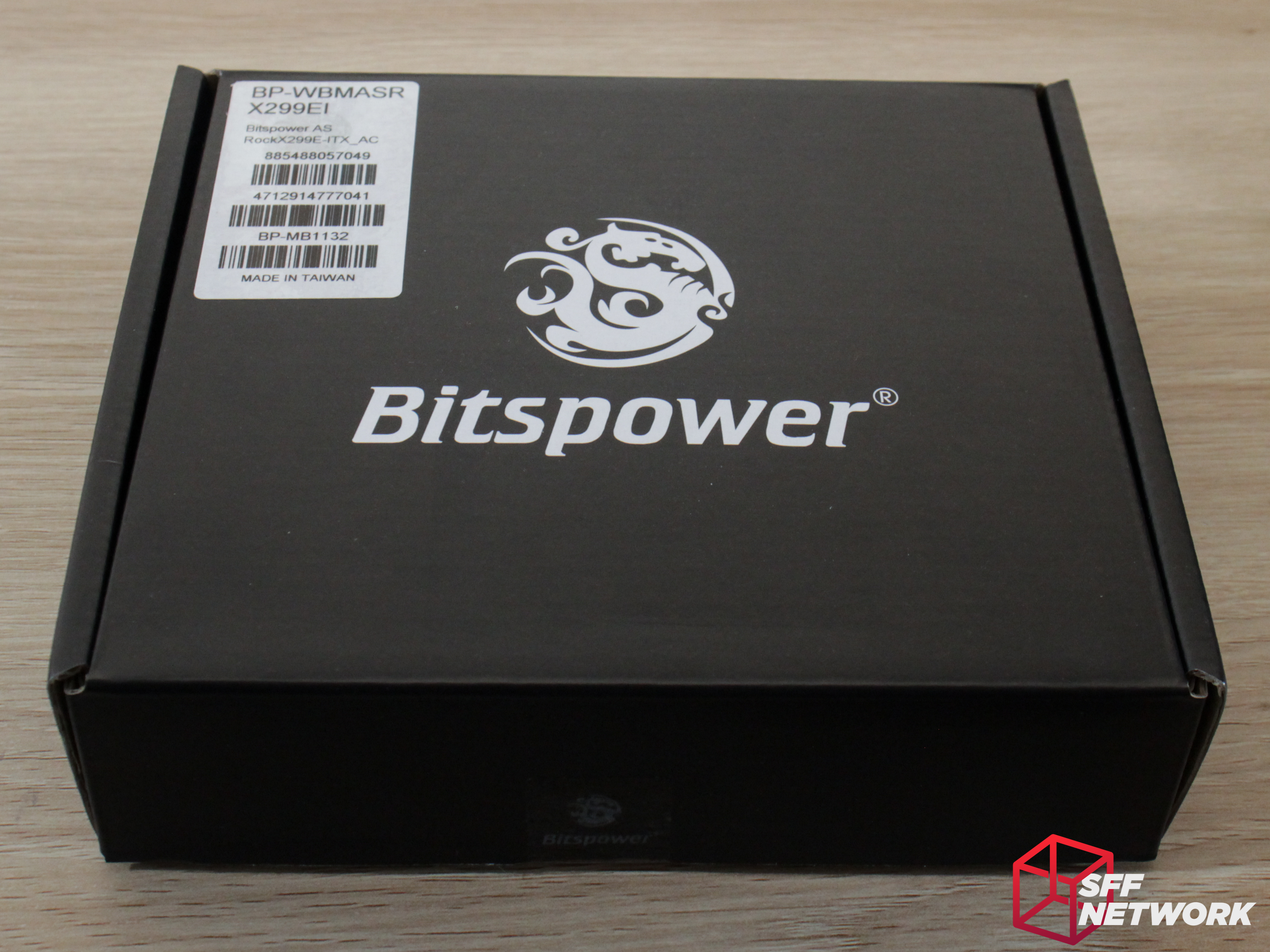
Along with the ASRock X299e-ITX/ac review unit, we were supplied a full cooling solution from Bitspower – including a 240mm Leviathan radiator, pump, reservoir and the all-important monoblock.
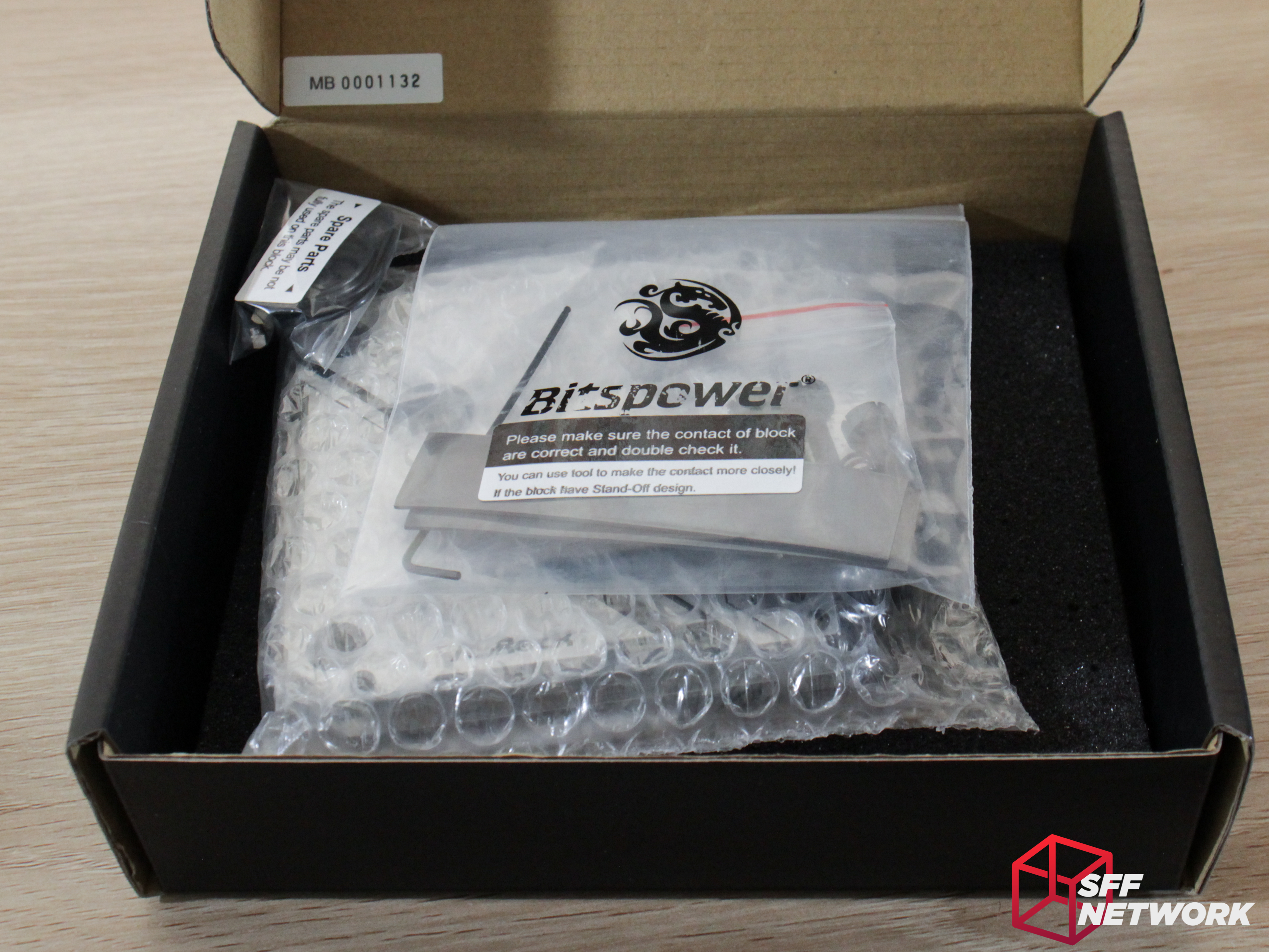
Opening the box, we are presented with the tool and accessory kit, and the block itself!
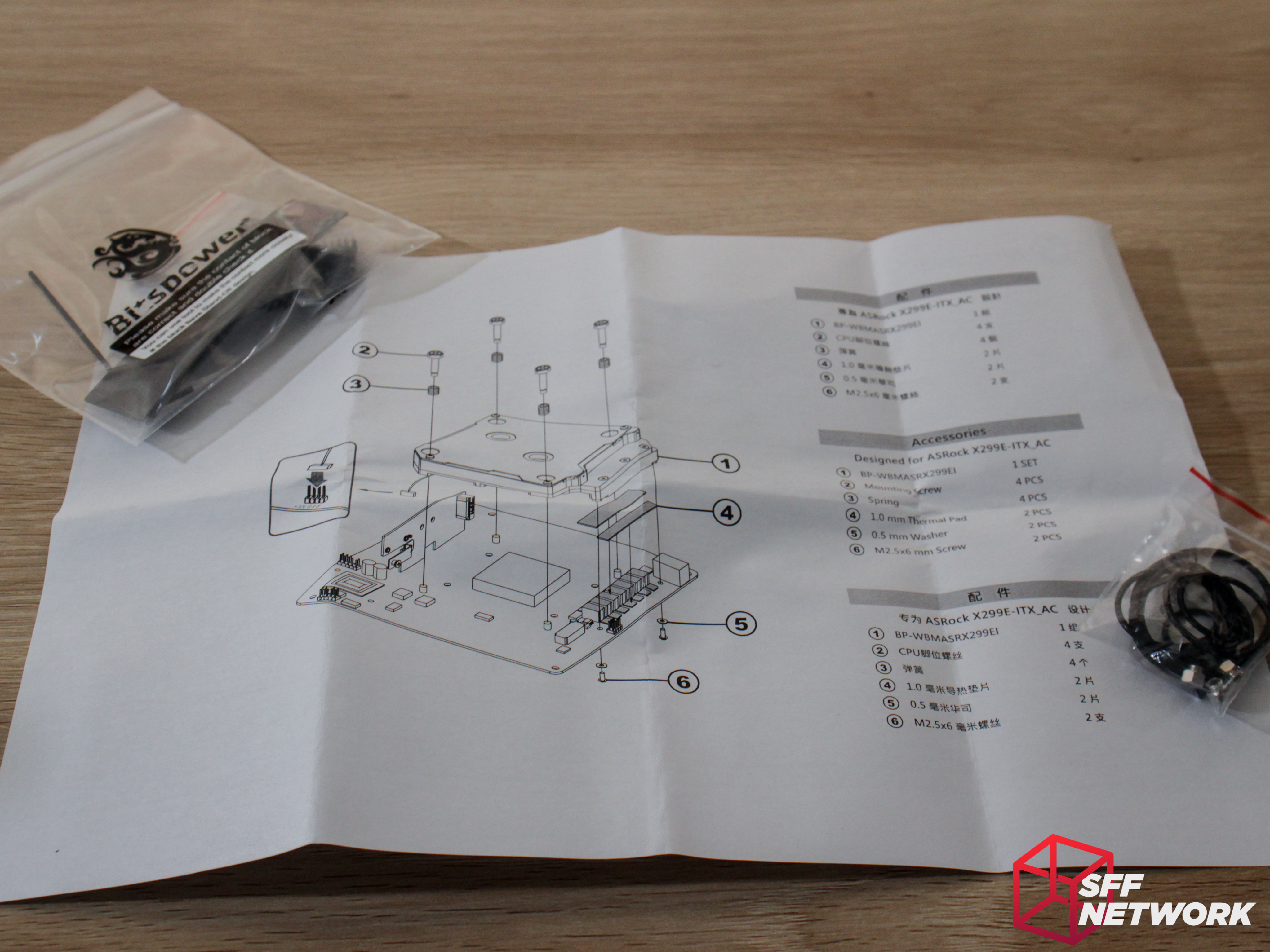
The instructions included with the block are pretty clear. The bag to the top left is the tool, thermal pad and screw kit, the bag to the bottom right includes a bunch of spare o-rings, screws and standoffs. I’m pleased Bitspower includes these – it shows they expect the block to be used long term.
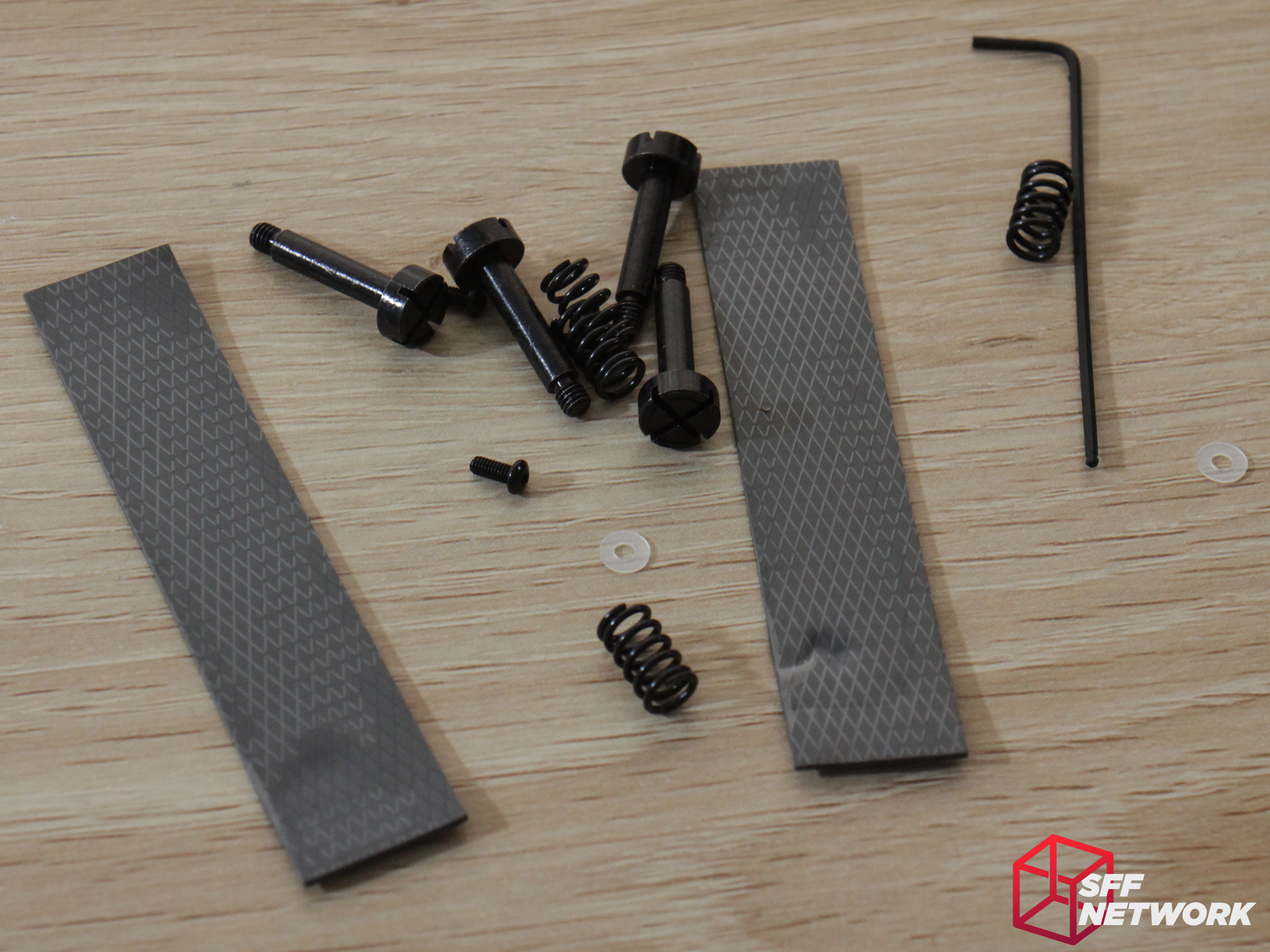
The included parts cover everything… except thermal paste! When installing the block, you will need to cut the thermal pads to size, so including an excess of these is much appreciated.
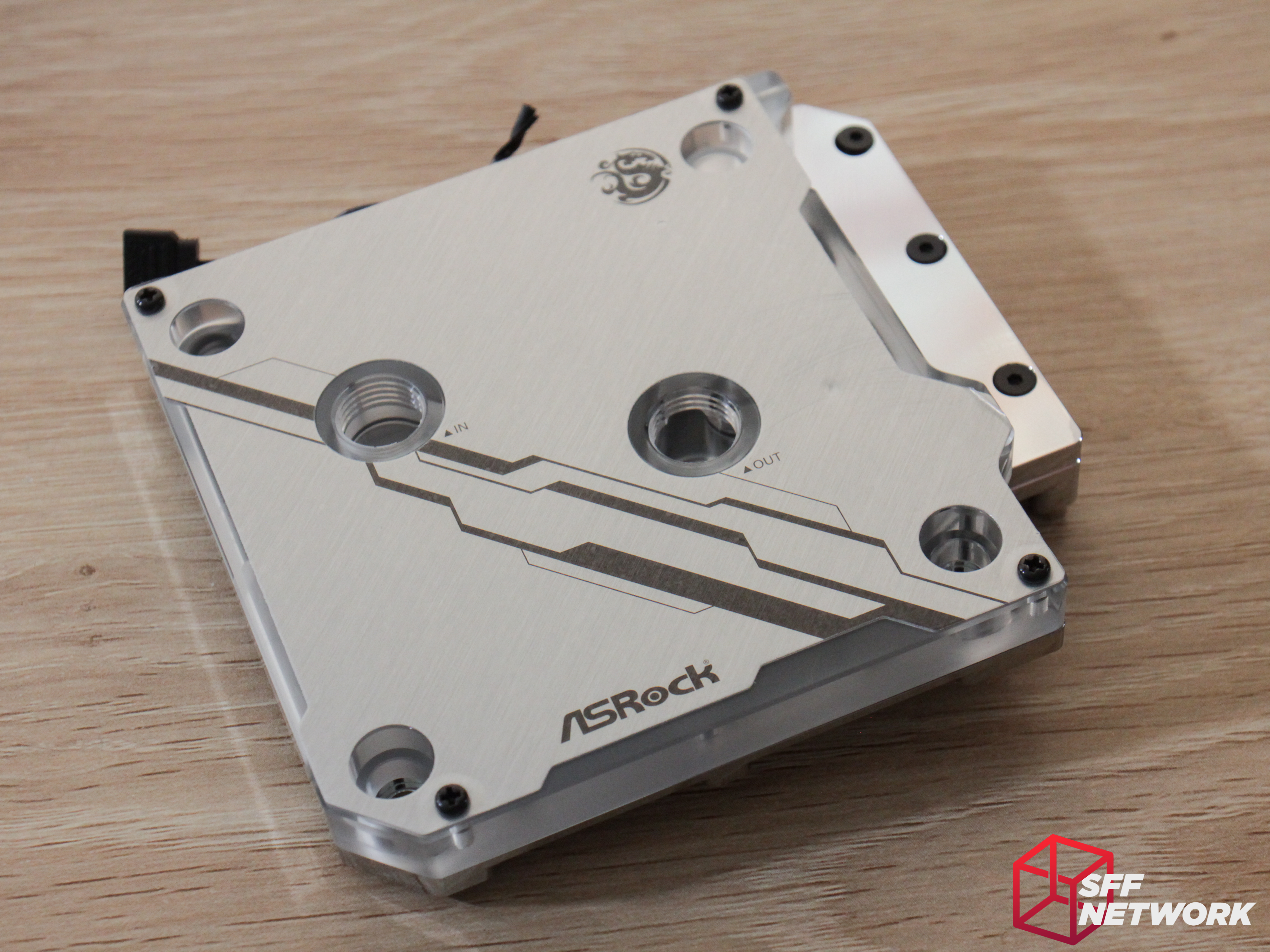
The block itself continues the subtle design of the board and packaging – no flashy graphics here. Clear markings of input and output are a nice touch, as it’s difficult to tell otherwise which way the water flow should go.
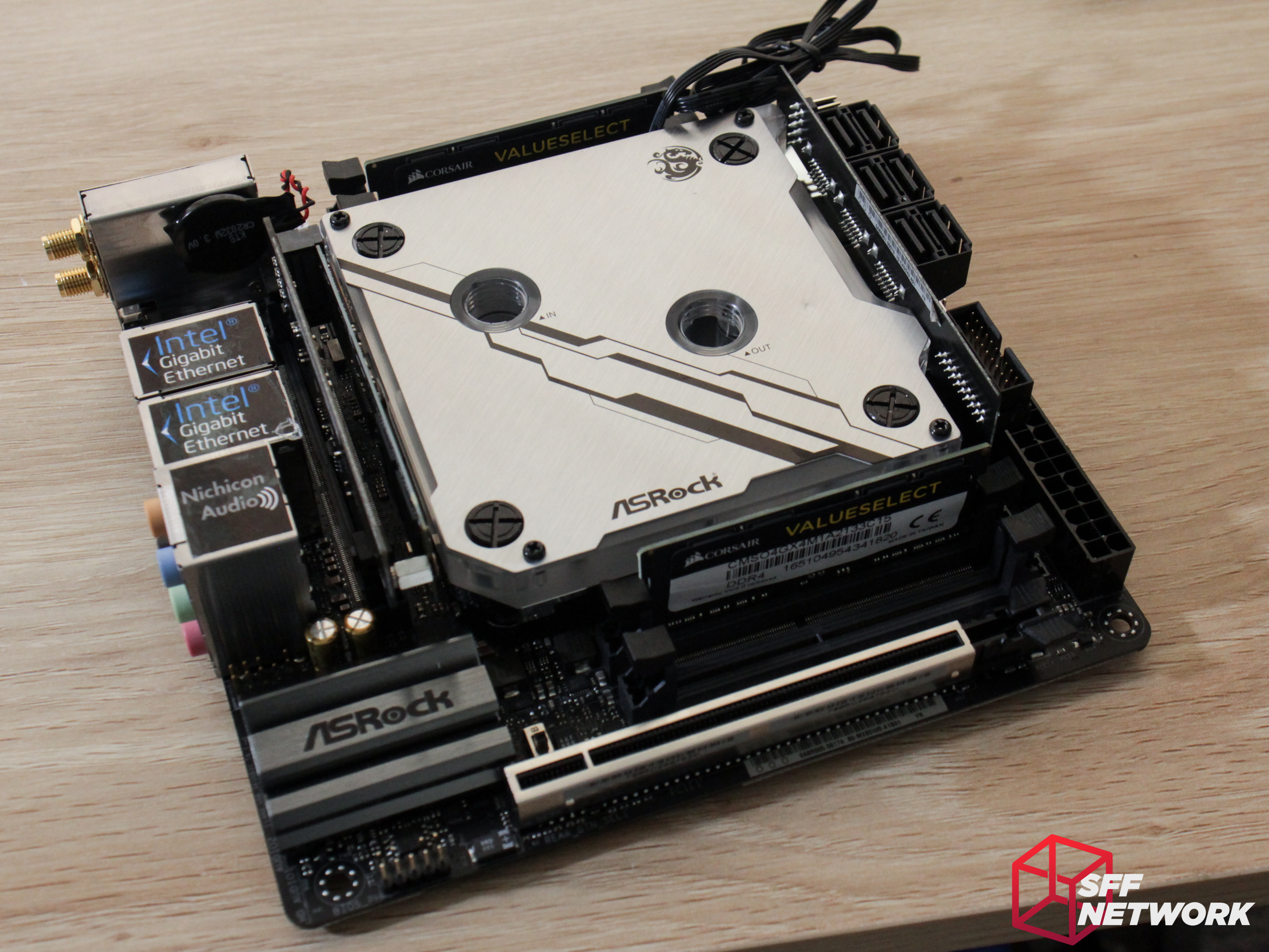
Shiny! The base of the block is polished to a high shine, with no machining marks visible on the contact surfaces. On this particular platform, using a monoblock instead of a universal CPU block, is worth the extra investment, as the VRM solution is incredibly dense and needs active cooling, be it from a fan or a waterblock.

Removing the VRM heatsink and front daughterboard allows us to cut and install two thermal pads – one for the inductors, one for the VRMs.

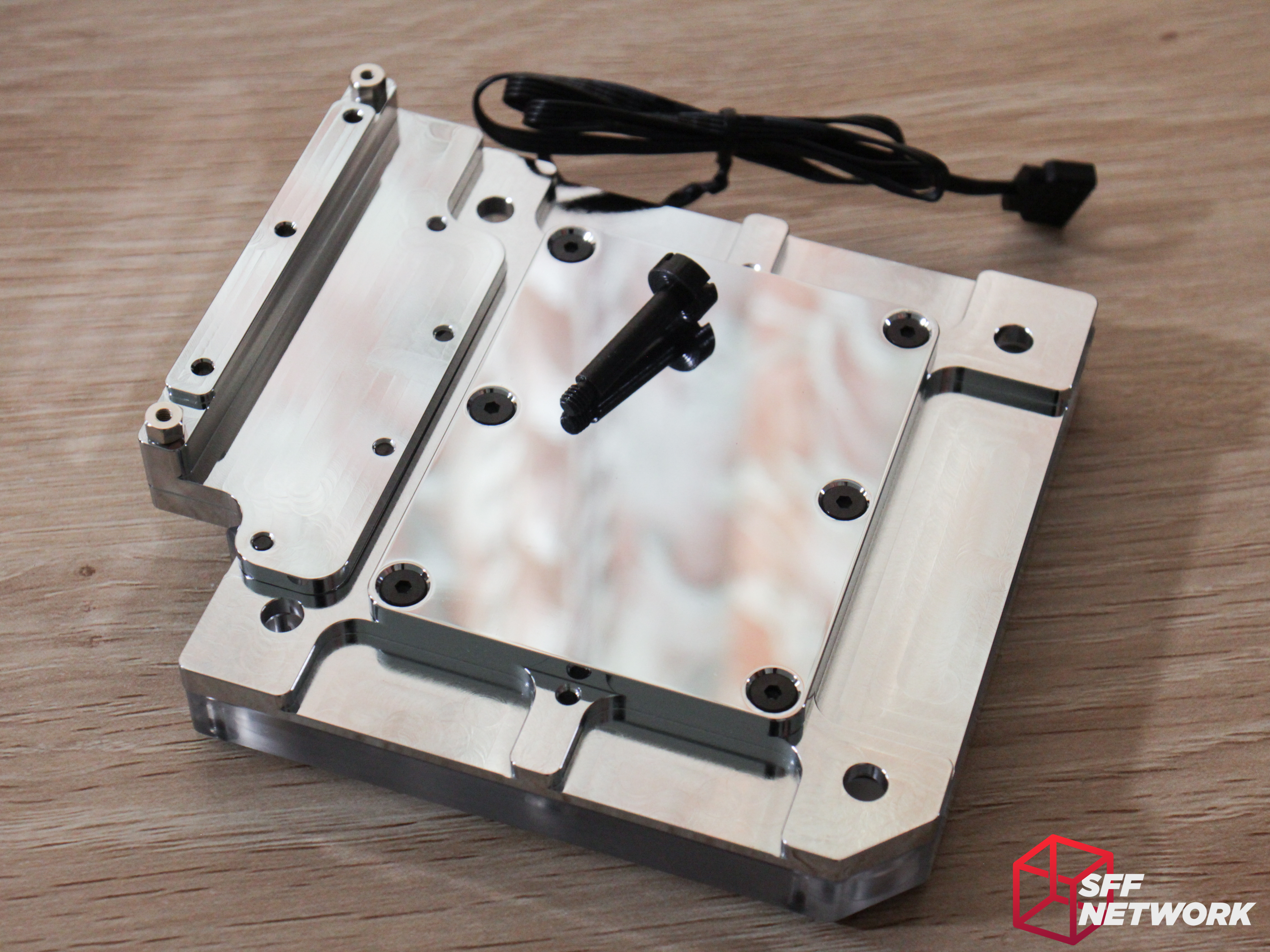
For those who are after an even more ‘custom’ look, the thin aluminium plate on the top of the block can be removed by unscrewing the four black Phillips head screws. The block itself is installed onto the board with the four large screws with the four provided springs to keep an even pressure across the CPU IHS. Two screws are then installed from underneath the board to add pressure to the VRM section.
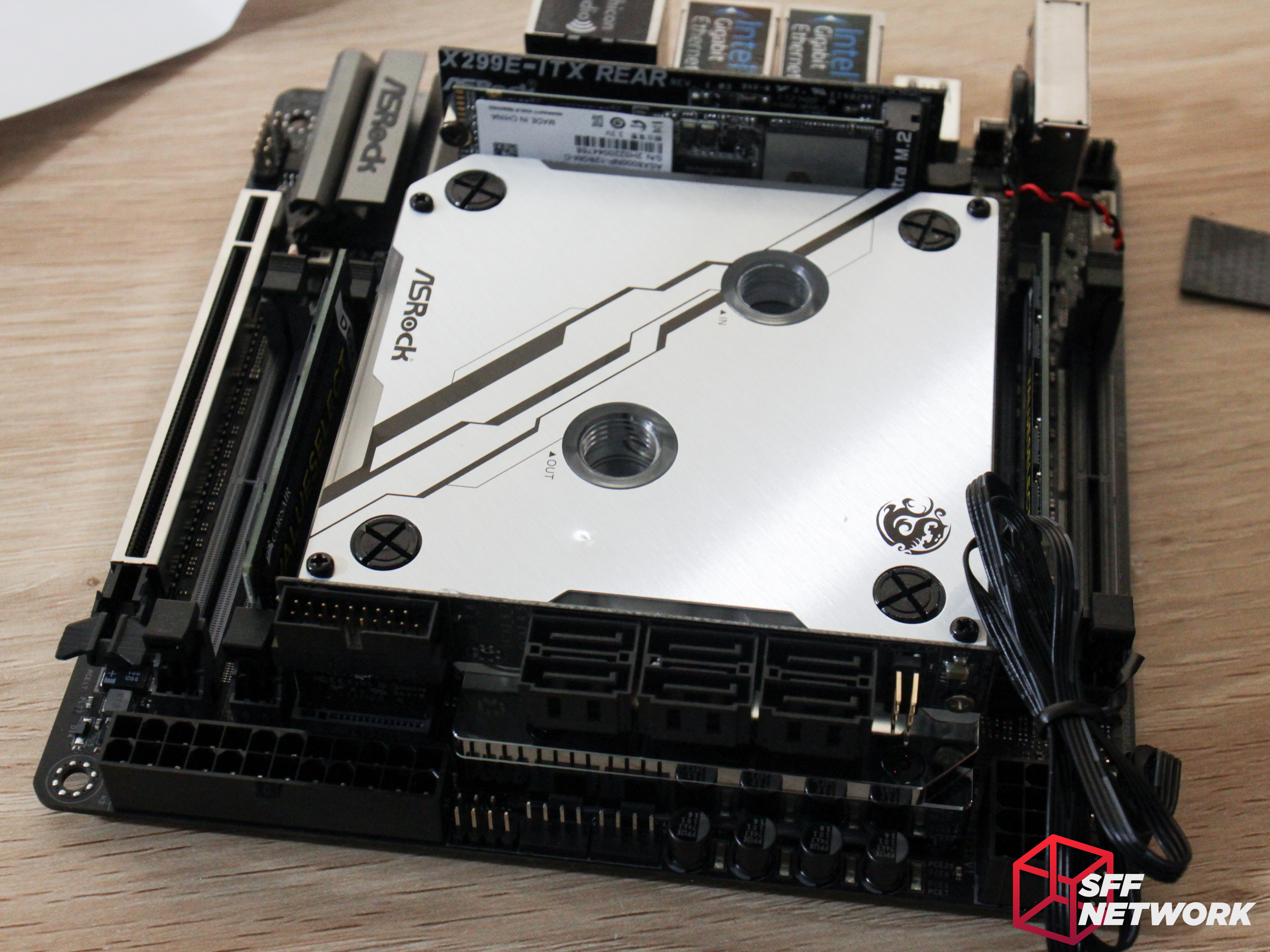
To complete installation, the front daughterboard can be reinstalled and screwed into the provided threaded holes in the block. This integration is a nice touch.
All done!

RGB, because of course.
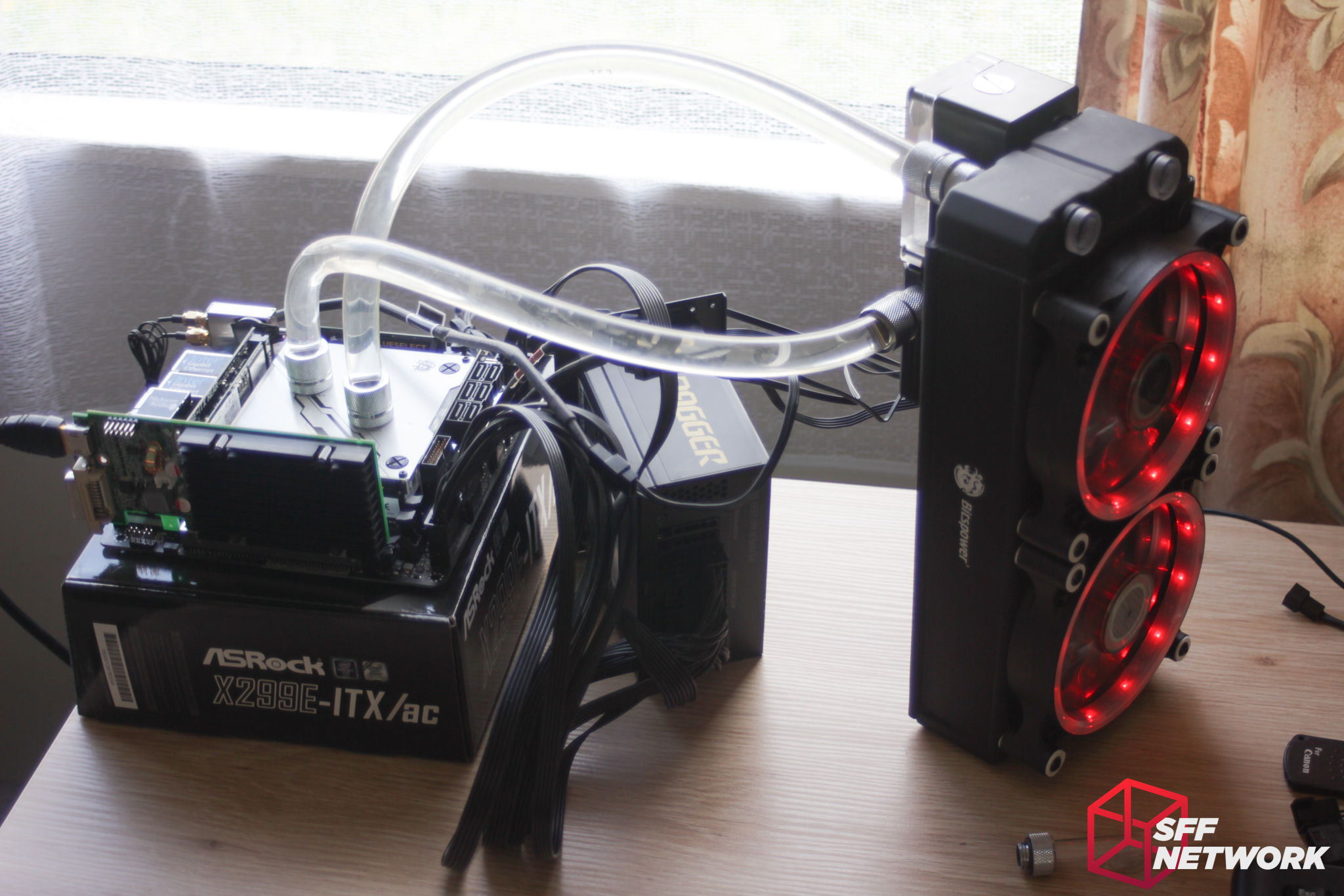
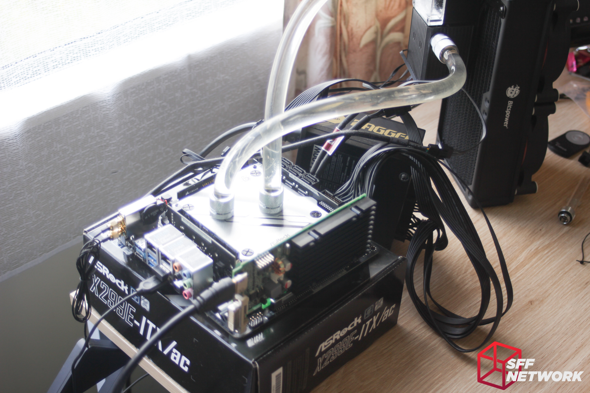
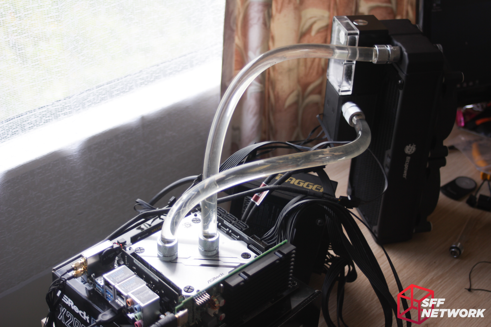
After some loop filling, bleeding and tweaking, we have our temporary bench setup running on distilled water. Bitspower’s Leviathan 240 radiator, RGB fans and pump/reservoir combination complete the loop, and create an impressive cooling setup. It is a shame though, that this configuration would be a challenge to fit in most SFF cases.
I did try and fit the loop in my NCase M1, with no luck.
The Testing
The testing of the ASRock X299e-ITX/ac comprised of many test configurations – from hardware to software. I covered a few core items that have raised concern from the wider community – notably the VRM temperatures, one of the major issues noted with the X299 generation of boards – they overheat very easily.
I also covered basic temperature testing under air and water cooling. Without a comparable X299 platform system to compare with, performance figures aren’t particularly valuable, so this section of testing was postponed until we have another X299 board to test!
The Results
Firstly, temperatures. Using the aforementioned Noctua NH-L12s cooler, I recorded CPU delta temperatures of 39°C. Not bad for a 140W CPU under Prime95 blended test load! The critical temperature to look at is the VRM section, since many other X299 boards don’t do well here. The motherboard reported a temperature of 22°C above ambient. That didn’t seem right for a VRM array, so this must be the chipset’s temperature. I used the ever-handy infrared thermometer and found the surface of the VRM heatsink to be sitting at 30°C above ambient, not bad. Measuring the temperature on the underside of the board in the VRM section returned a result of 35°C above ambient.
Throwing the water cooling loop on the board reduced the CPU temperatures to 21°C delta, and a reported motherboard temperature of 24°C above ambient. The increase in motherboard temperature here is most likely due to there being significantly less airflow over the board. I found the VRM area temperatures to be closer to the CPU temperature this time around, with a delta of 24°C on the VRM section of the waterblock, and 25°C underneath the board. Woo water!
Delta temperatures (difference between ambient temperature), all measurements taken with 100% fan speeds.
| Component | Air-Cooled | Water-Cooled |
| CPU | 39°C | 21°C |
| Chipset | 22°C | 24°C |
| VRM heatsink | 30°C | 24°C |
| VRM underneath | 35°C | 25°C |
Mind you that even at 100% fan speeds, both setups were reasonable noise-wise.
A bonus test I performed was one that I’m sure you have been considering – will the board boot without the daughterboards? Well…
Yes. The board will boot without the boards installed – at a cost though. Without the front daughterboard, all you lose is the SATA ports and front panel USB3 and USB2. Minus this functionality, the board runs fine!
Removing the rear daughterboard causes quite a few issues. None of the rear USB works, and neither does the ethernet ports. This isn’t surprising, considering the controller chips for these ports are on this particular daughterboard. Booting without this board dumped me into the UEFI environment, and I was unable to do anything.. mostly because the input devices I was using were USB!
The Bifurcation
To test support, I use an Ameri-Rack ARC1-PELY423-CxV3 riser, which is an active riser, using the P16C20400SLE chip, some passives, and a flexible ribbon cable. In addition to this, I install an EVGA GT210 GPU and a RAID card (PCIe x4 card) or a Realtek NIC (PCIe x1) in the two slots on the riser. I test in both configurations (hence using the single slot card!).
In “Auto” mode, I had no luck with bifurcation. However, setting “x8, x8” mode in BIOS enabled the bifurcation to work successfully in any configuration! Untested but potentially interesting for those quad M.2 cards without a PLX chip, is also the “x4, x4, x4, x4” bifurcation setting, but we currently don’t have the hardware to test this.
The Conclusion
The ASRock X299e-ITX/ac is a posterchild for SFF systems – a motherboard with very few compromises in a tiny space. A fully featured “Little Monster” has reached the market place at a price of just under US$400 (on Newegg.com), highlighting its uncompromised premium feature set and build. This is a high end board for a high end CPU ecosystem. All the features you could want are available on the board, barring Thunderbolt.
However, with Ryzen’s ecosystem, the X299 platform has lost some of it’s shine, with only those needing huge core counts needing Skylake-X’s power, but it also comes with an increase in TDP. Intel’s VROC kerfuffle, HEDT pricing and Kaby Lake-X vs Skylake-X market segmentation does knock some of the lustre from the ASRock X299e-ITX/ac’s brilliance. This is a shame, as the board itself is a marvel of engineering.
If you are wanting the current flagship motherboard of the SFF world, the X299e-ITX/ac is it. However if it’s out of your price range, fret not as slightly lower performance and feature sets are available for a significantly lower price. The choice will depend on your use case, whether or not you need 64GB of quad-channel RAM or up to 18 CPU cores in a tiny package.
Pros
- Great connectivity options
- LGA2066 on M-ITX, with quad channel memory, no less!
- Front daughterboard can be removed with no major issues, barring the reduced ports
Cons
- Airflow issues with the daughterboards and memory forming a mini box on the board
- No Thunderbolt
Niggles
- Price, but you do get what you pay for!
What are your thoughts? Wondering about tested hardware and cooling configurations ? Join us over in the forum!