Hi,
This is a longer version of "what were you up to today", which I think relates loosely to our common hobbies, but it's still off-topic.
'cause we're not all experts, people!
We are all normal people. It is perfectly natural to want to have an ortho-linear keyboard, you know, for the ergonomics and for the alignment of the fingers. All the kids want one.
[SPOILER="ortholinear"]
 [/SPOILER]
It is entirely reasonable to want it to be split as well, in a compact wooden case which you can eventually varnish, with two independent micro-controllers for each side. Like I said, all the kids want one.
[SPOILER="In the grass"] [/SPOILER]
The problem comes when one day, you start noticing that the USB connector to your main Arduino is starting to get loose:
[MEDIA=vimeo]462307682[/MEDIA]
It doesn't take long search on the Internets, to realize this is a common problem with this micro-controller.
It is perhaps time to debug the issue. But it turns out, when one is not technically skilled...
[SPOILER="one doesn't JUST desolder a Pro Micro"]
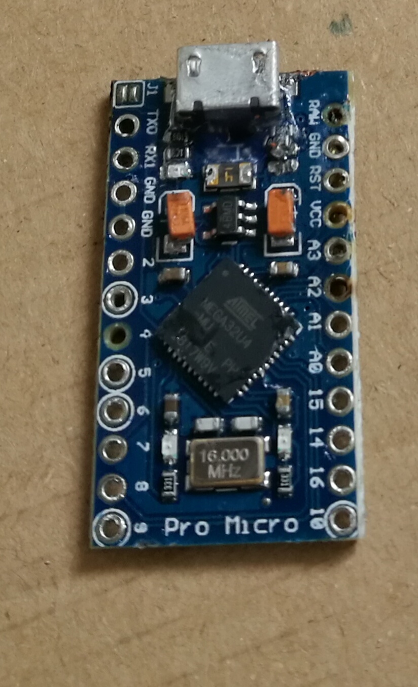
Upon inspection, I can see also that one of the resistors (the one next to GND) is completely out of place which happens to be used for the LEDs. Could be a coincidence, could be that I did it during the soldering.[/SPOILER]
Luckily, Pro Micros are relatively cheap compared to a keyboard and you can buy a bunch of spare ones
[SPOILER="New and old Pro Micro"] [/SPOILER]
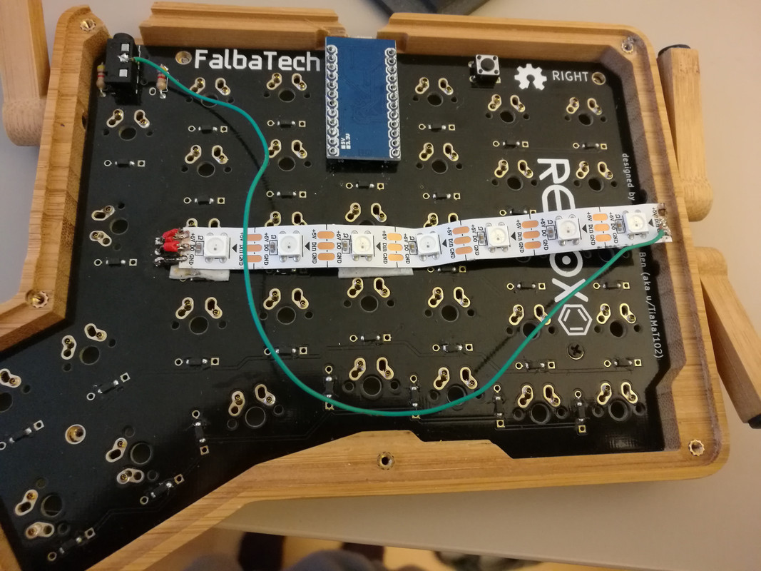
After the new Pro Micro has been soldered in, it is time to diagnose the patient. The patient seems to be doing all right except for a severe lack of RGB.
[SPOILER="The doctor diagnosed a lack of Voltage Common Collector along the diodes"] [/SPOILER]
Perhaps we should try to solder this again but, shouldn't there be a better way of doing this?
[SPOILER="VCC and GND cross over"] [/SPOILER]
[SPOILER="I mean this thing just doesn't do what I want, does it?"] [/SPOILER]
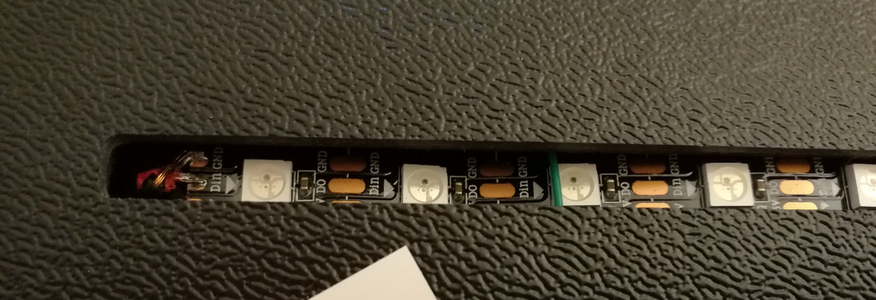
[SPOILER="Let's find out all the wrong ways of doing this"]The current must flow in the direction marked by the arrows, for the diodes to work. Clearly this is the opposite direction
 [/SPOILER]
[SPOILER="Adhesives can't help, because they melt much earlier than the time when the temperature for soldering is reached."] [/SPOILER]
The proper way of doing this would be with cable guides, passing the cable along the PCB and soldering the ends of the cable pin.
[SPOILER="But this is a SFF keyboard case"]Just the connector itself is already thicker than the whole space that we need for the diode + cables
 [/SPOILER]
The doctor couldn't save the patient's diodes...
[SPOILER="A sad day for the diode race"]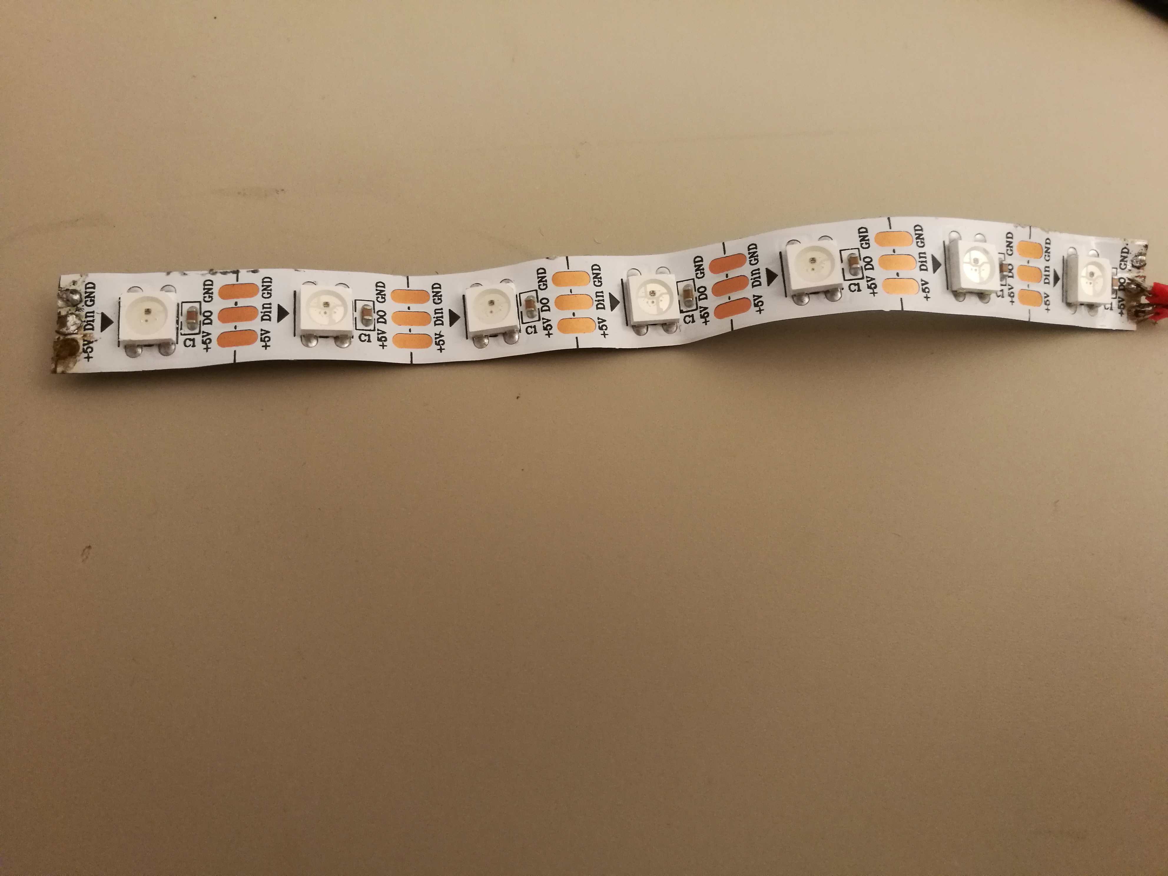 [/SPOILER]
We have no choice but to perform a diode transplant to the patient.
[SPOILER="These diodes hold the promise of a beautiful future for our PCB"] [/SPOILER]
Finally, after realizing that the soldering temperature is too high for certain cables and they bent too much, I went for sturdier cables, which I bent in the shape I wanted before soldering:
[SPOILER="Sturdier cables"] [/SPOILER]
And they happily match the cover at first try.
Kids these days need little amount of keys, and if more are needed, they are organized in layers. Kids these days also can remember their keys and layers by heart. But I need reminders.
[SPOILER="I use colored markers to differentiate the red function layer."] [/SPOILER]
And thus, we can use RGB to identify in which layer we are currently in:
[MEDIA=vimeo]462307710[/MEDIA]
And the patient lives!
I want to mention and thank [USER=11797]@SiKiaTriK[/USER] as well for some soldering tips and encouragement.
