
This guest editorial has been written by forum member and vendor SaperPL!
All opinions in this article are that of the author, and not necessarily those of SFF Network or the team.
In context of external power connector placement
Foreword
This is a lengthy article because the problem that I’m trying to explain in it is a bit convoluted.
The point of the article is to start a discussion around the card designs in context of both SFF builds and mainstream ATX builds together, for the sake of eventual new design coming out of such discussions being noticed by industry professionals, to be able to gain enough adoption to survive long-term on the market.
Riding the tide
In the PC components market, we rarely see interest from component manufacturers in changing or reinventing the form factor of a specific component type while still making the part compliant with the rest of the PC components ecosystem.
Usually it’s more about trying to reinvent something in a way the company can make this proprietary to control the ecosystem, which usually ends up not being used by everyone else. It’s this kind of situation where we have X number of standards that don’t mesh well together and someone comes in to make a new standard that will unify all existing standards, and we end up with X + 1 number of standards that don’t mesh well together in the end.
But now it seems that “stars have aligned” for us, showing the interest of some of the graphics card vendors in reinventing the card power connector placement while also NVIDIA showing increased interest in the SFF market by introducing the SFF-Ready program, however misguided it is. It is this kind of situation where the community of us, PC builders, could see it as an opportunity to voice our opinions and ideas on what the next standard of graphics cards should look like.
Stealth cable designs—the opportunity to catch
With a trend of hiding all the cables while making the interior of the case clean for showcasing through the tempered glass panels, we are seeing some attempts at changing form factors of the motherboards and GPUs to adhere to that trend.
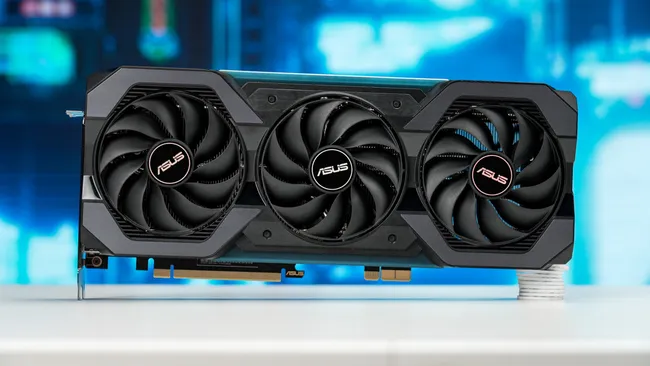
One of such attempts is ASUS’ custom power connector for the cards, which is generally a really bad idea for the consumers to get locked up in such a proprietary solution, but it proves a point that both if the card partner wants to, he will move the power connector location and also that it can be at the bottom of the card. So this is a proof of concept that it is possible to move it around the card.
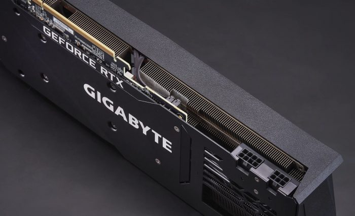
Gigabyte has made cards that have connectors facing straight down from the PCB, which is good for some SFF and tower cases that have room for the cable to bend, but not all cases will have it.
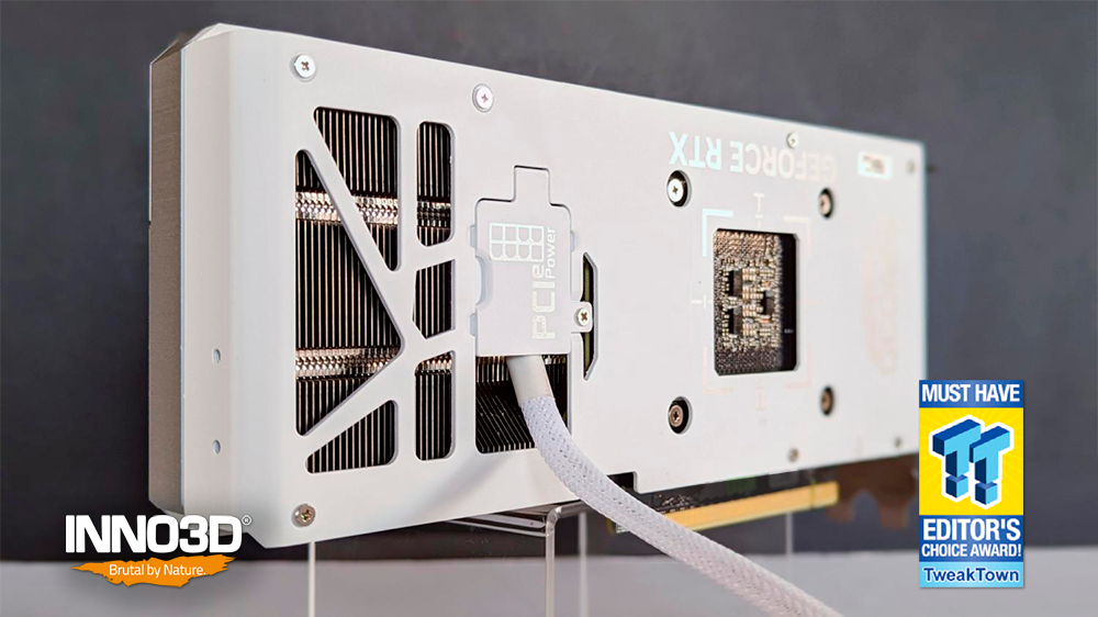
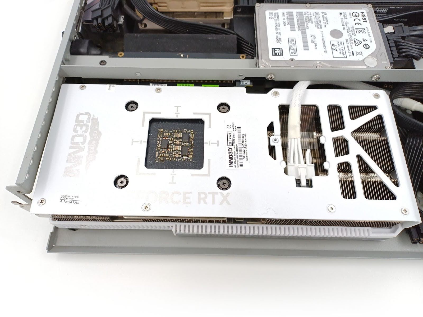
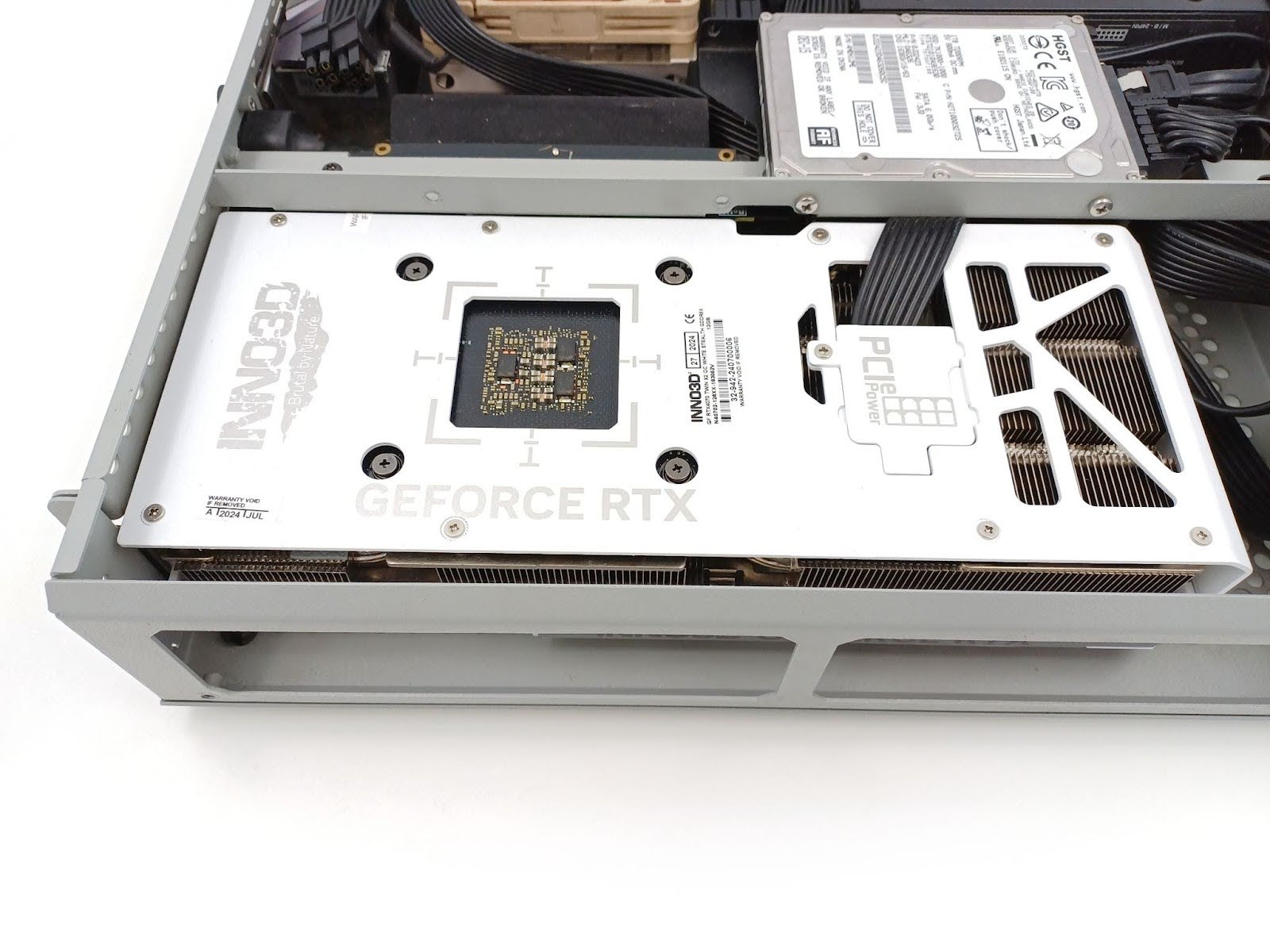
Another such attempt is Inno3D’s Stealth cards with power connector pointing downwards, which may work okay with an ITX board, but if you think about the ATX board, how tightly would you have to bend those cables sticking out right on top of the board? So it’s good for us—the SFF community—but not for the general consumer, still being the majority that wants to use a full ATX board, and if we want to ride the tide of change, we need a unified solution for everyone.
The production card, however, seems to try avoiding this ATX problem by going out of the backplate to avoid collision with the motherboard, so it’s not there yet for us unless we can shave some portion of the radiator to pass the cable through it:
Note however what advantage for the SFF all of these solutions have: the cable is not sticking out at the top nor at the back of the card, which means the external outline of the card should be the exact dimensions for fitting the card in the system—no figuring out how much space we need for the cable as long as the dimensions are understandable.
So we are, or more like ASUS’, Gigabyte’s, and Inno3D’s designers are onto something when it comes to being more SFF-Friendly, but they are not there yet in making their product being a general use case GPU that could go mainstream, because they are introducing new restrictions along the way.
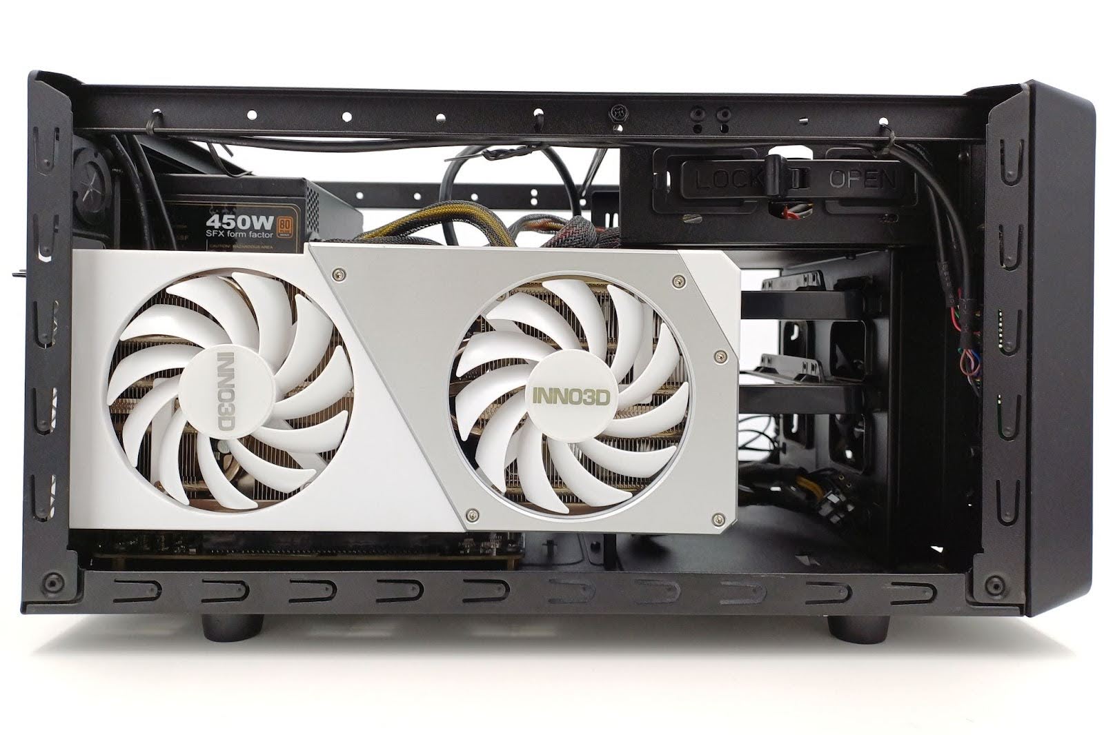
Inno3D Stealth seems SFF friendly, but not ATX friendly
Inno3D’s card is actually SFF-Friendly when it comes to standard layouts without the riser and the popular back-to-back sandwich designs that do have an opening in the middle wall, often called a spine, meaning there’s a hole in the surface separating the GPU from the motherboard/power supply compartment in the gap between the motherboard and power supply.
Note that the cable needs to either pass right next to the edge of the motherboard or there needs to be a big enough gap so it can be routed down behind it, which can get tricky with thicker cables like the one included with the card.
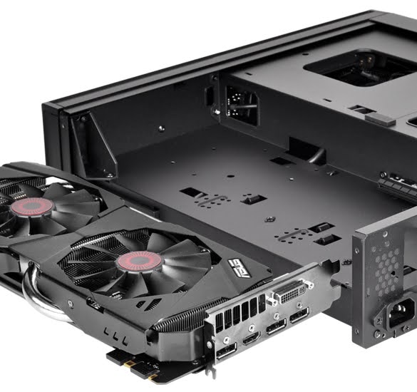
The problem is, not all cases and configurations allow that cables to pass through at the back of the card. For example, in SILVERSTONE RVZ02, there’s a solid wall behind the GPU:
Sentry 2.0 will also have some problems with thicker cables (card below can’t be plugged in correctly):
Note that the cover in Sentry 2.0 has a wall that is close to the back of the GPU to reduce the amount of air that could circulate around the card. The cable connected here is the end connector of the split pigtail two connectors; connecting the first connector would mean two ribbons and twice the thickness to fit.
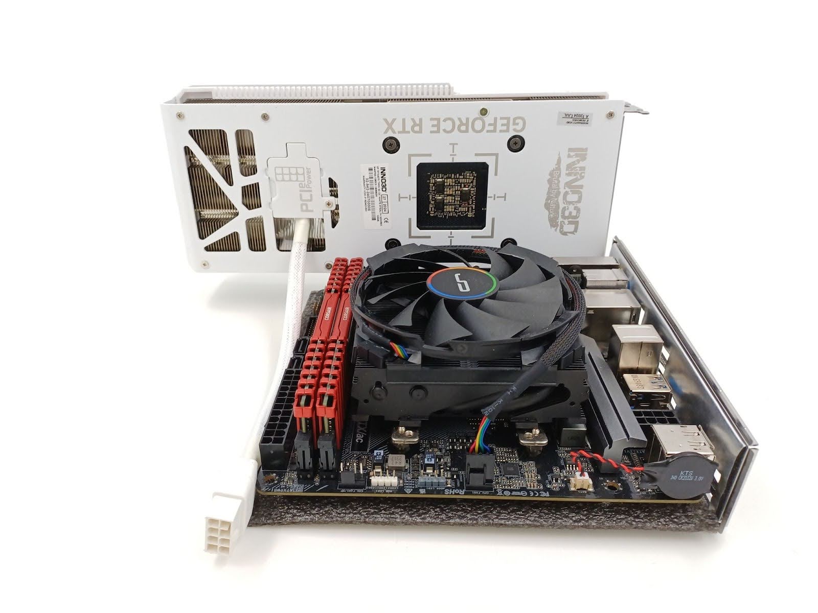
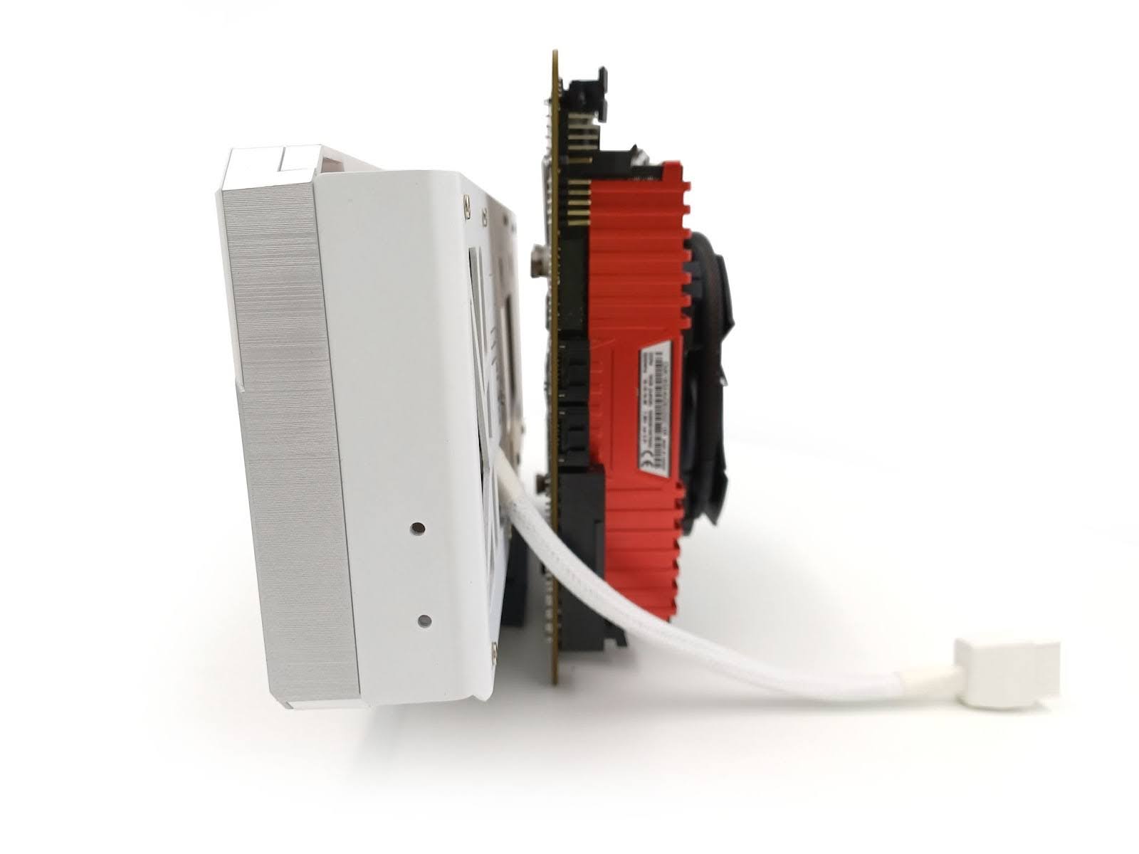
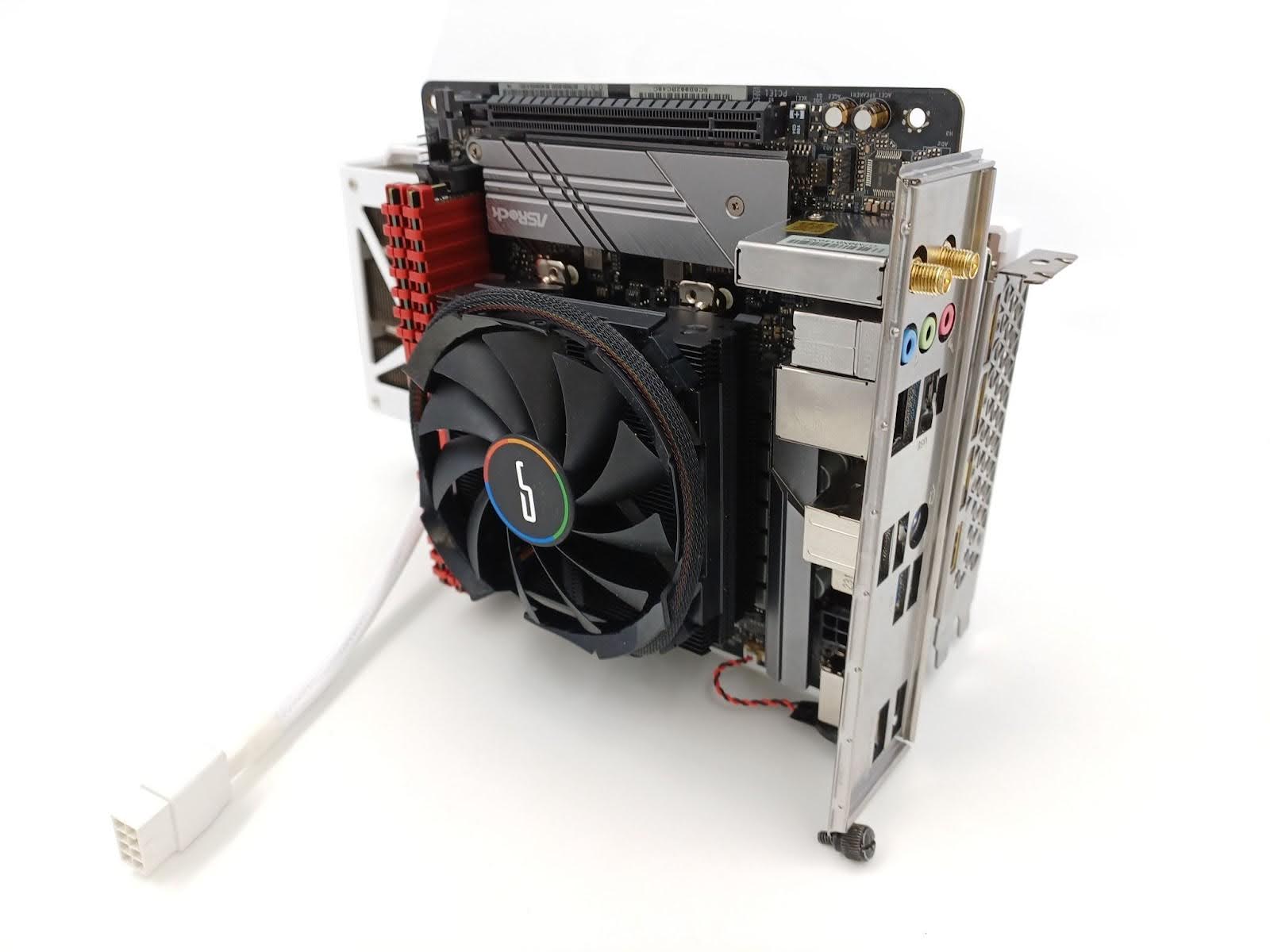
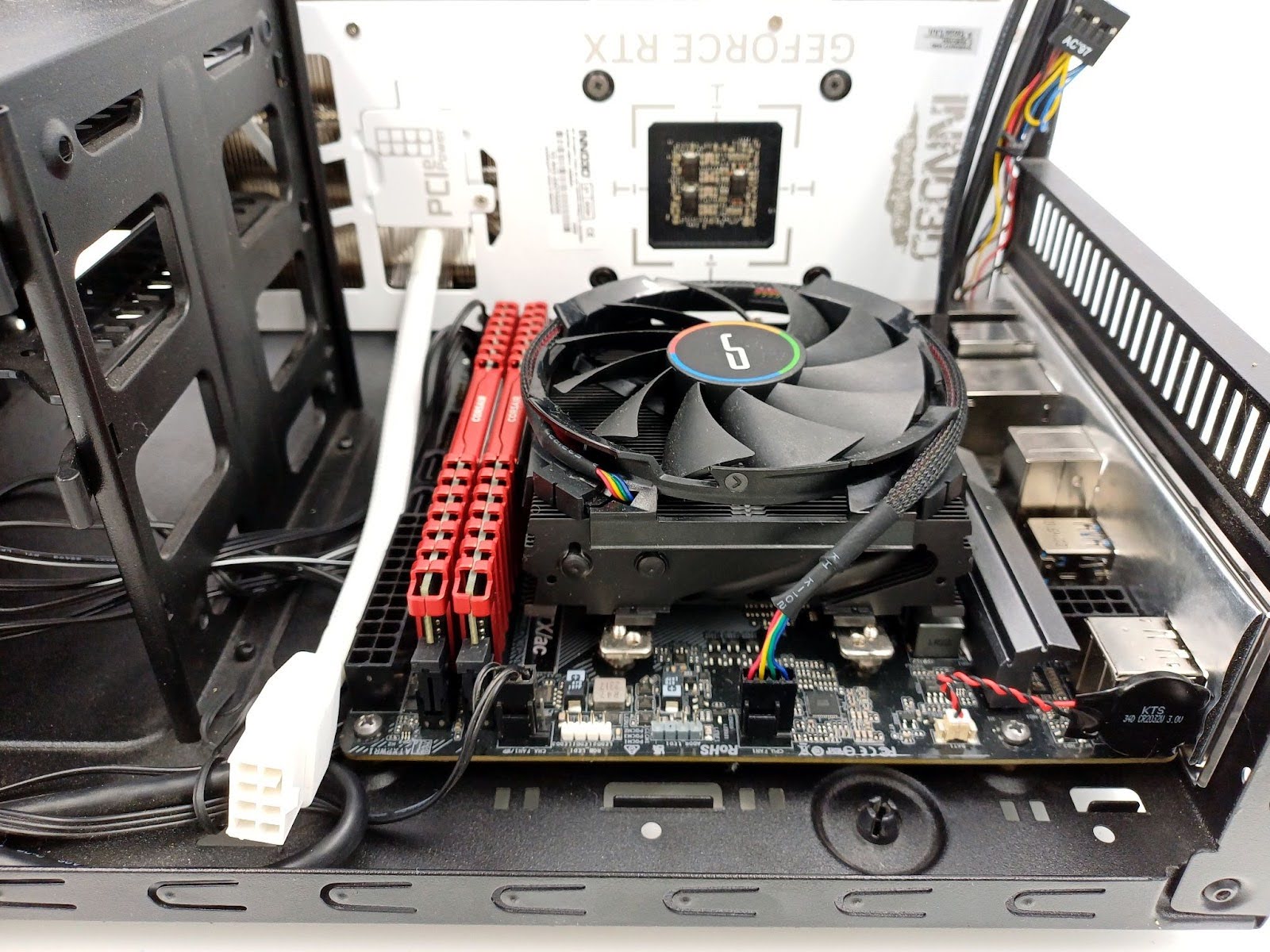
The problem with this design, however, is that with a full ATX motherboard, it’ll cause issues with routing the cable, and it won’t really be a stealth/hidden cable for those builds anymore.
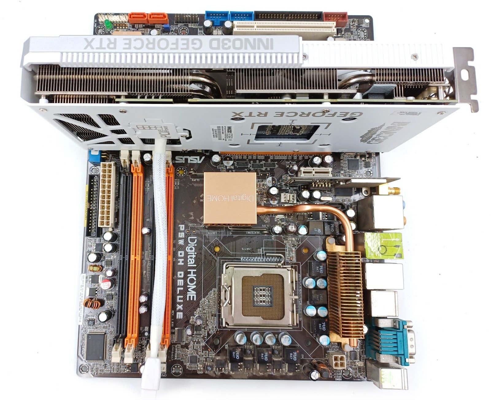
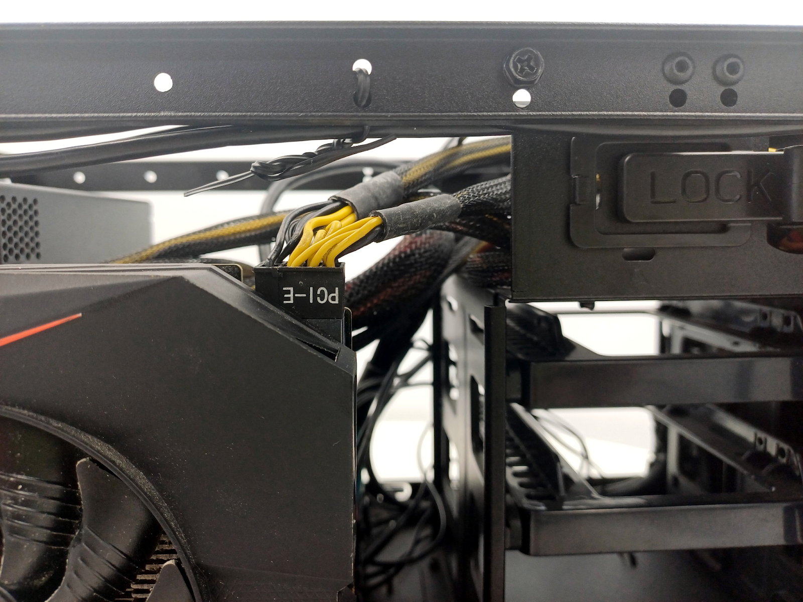
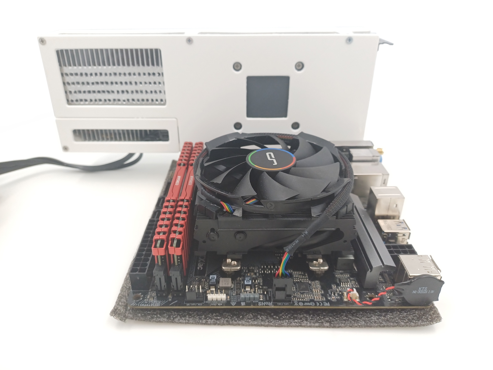
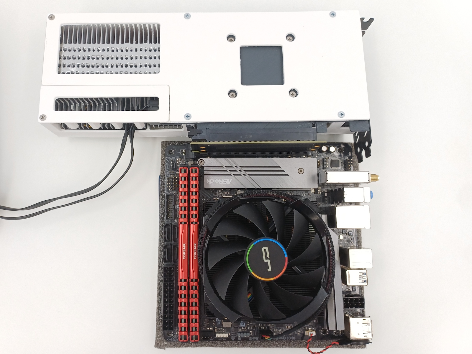
The cable comes in front of the memory section on the ATX board, so with tall memory modules and a beefy CPU cooler (example below) reaching both the slot and the memory modules, the cable will either have to be somehow squeezed down under the cooler or under the card to be routed out.
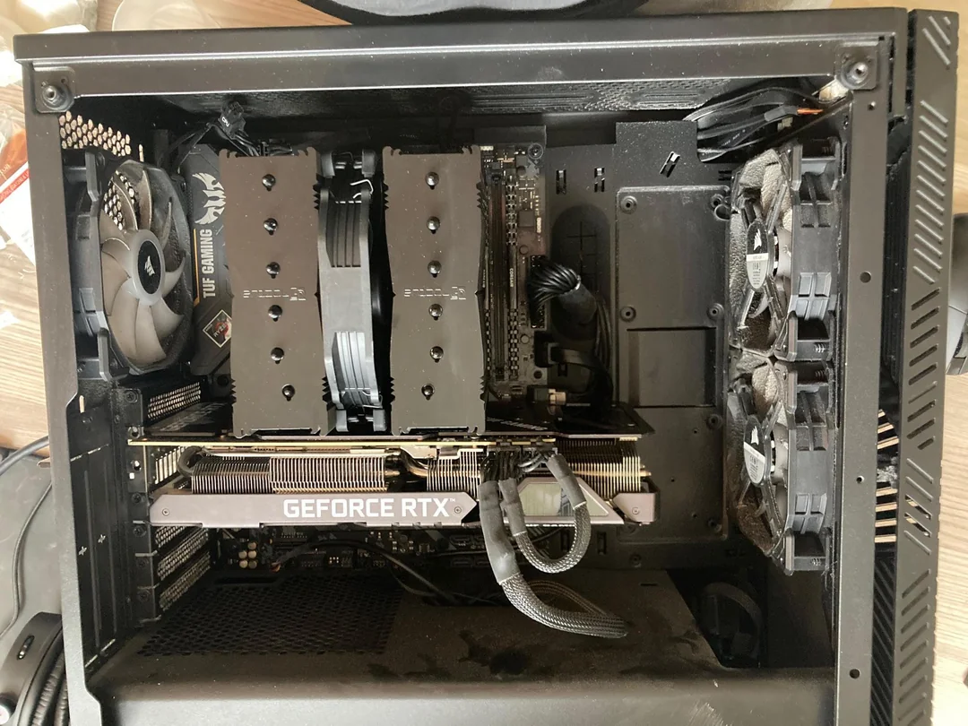
With this design, the card needs some space to the adjacent surface, like a cooler or another card already, but note that we have the old 8-pin PCI-E power connector here.
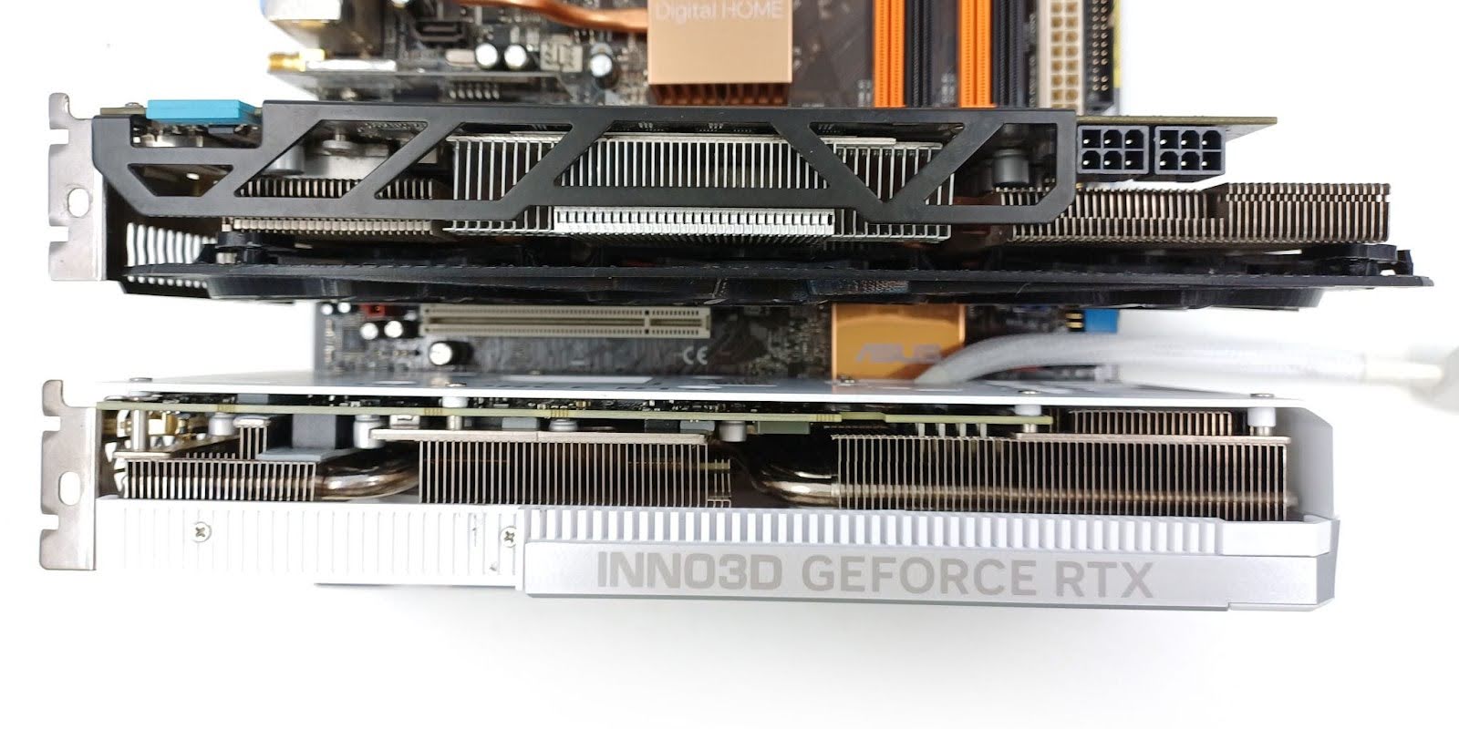
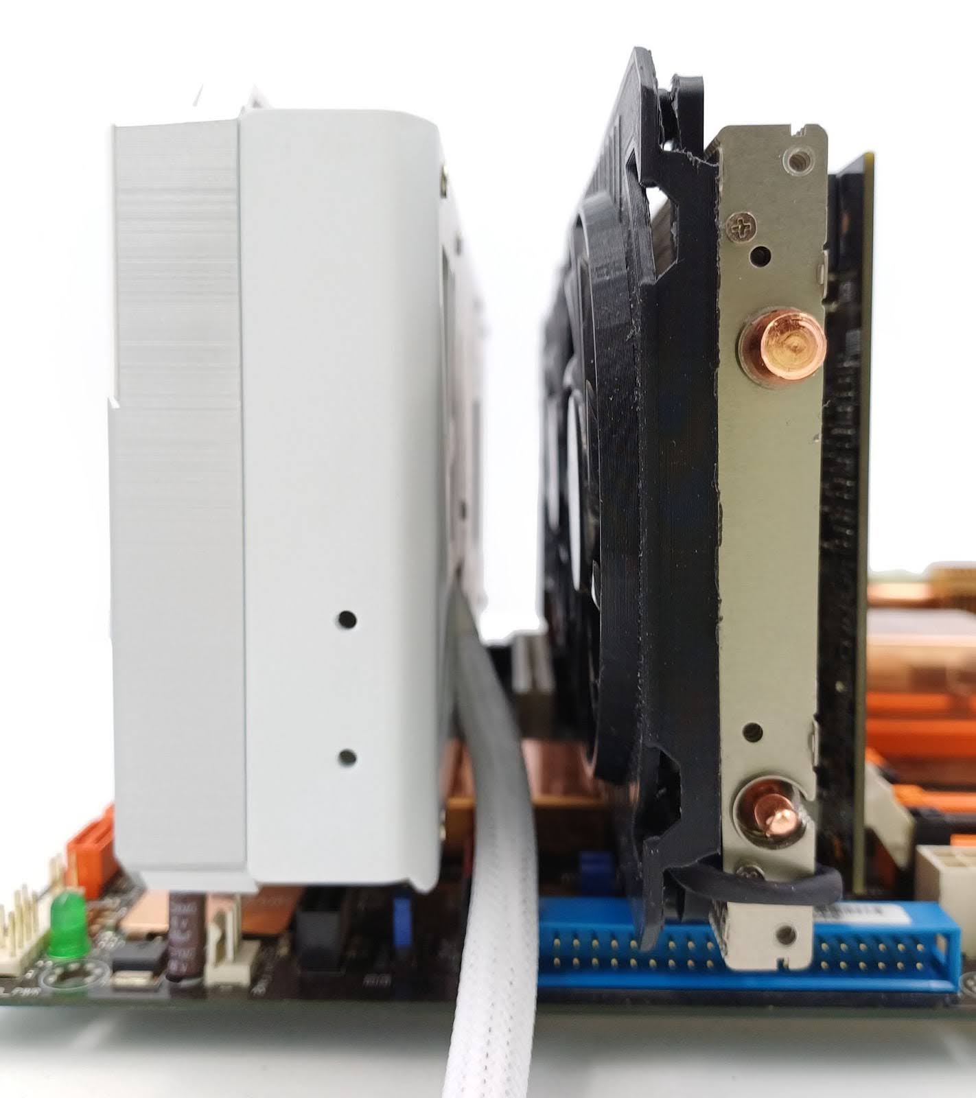
Think about how much space we may need here to safely twist 12VHPWR cable with this design.
Overall, the Inno3D’s stealth cable design is good for most of the SFF configurations, but if it’s not going to get a wide adoption outside of the SFF niche, we may not see cards with this design after one or two generations anymore, especially with the 12VHPWR connector creeping into the RTX 4070 TDP range.
If you are hoping for this design to stay with us for longer, and your specific SFF build configuration supports it, and you are planning to upgrade your GPU to RTX 4070, then I would strongly recommend considering picking this card over other cards. If it doesn’t sell well in this GEFORCE card generation, it may get discontinued by Inno3D without a chance for better, improved design for the next generation of cards.
What’s up with the space for cables in SFF anyway?
Bringing NVIDIA to this topic here: the SFF-Ready program is obviously driven by the 12VHPWR cable space requirements for a safe bend near the 12VHPWR connector, so maybe a solution that removes the cable space requirement from the equation is also something that NVIDIA would be interested in?
Why does the power cable make so much of a mess in the SFF card-to-case matching that a most valuable public company in the world can’t or doesn’t want to solve this problem?
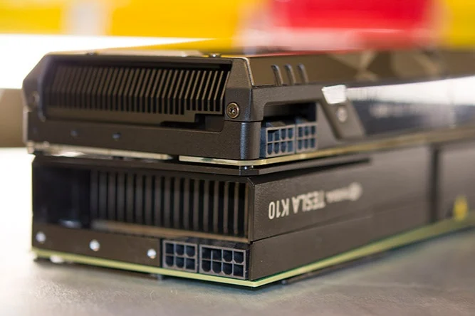
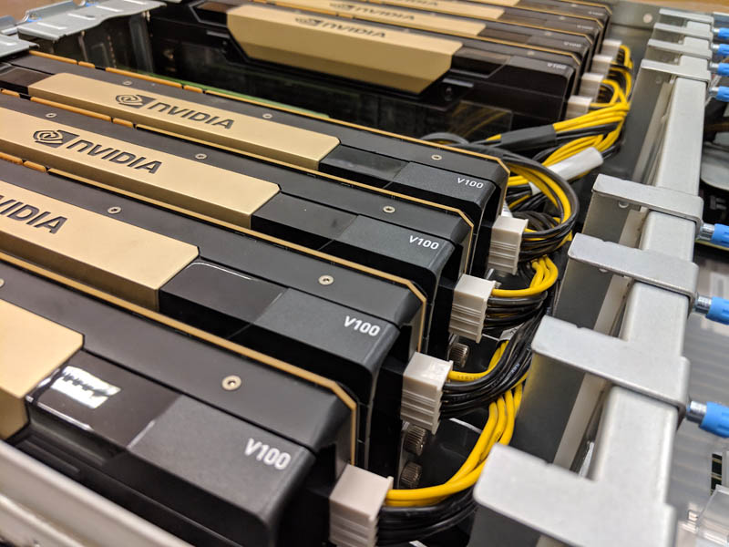
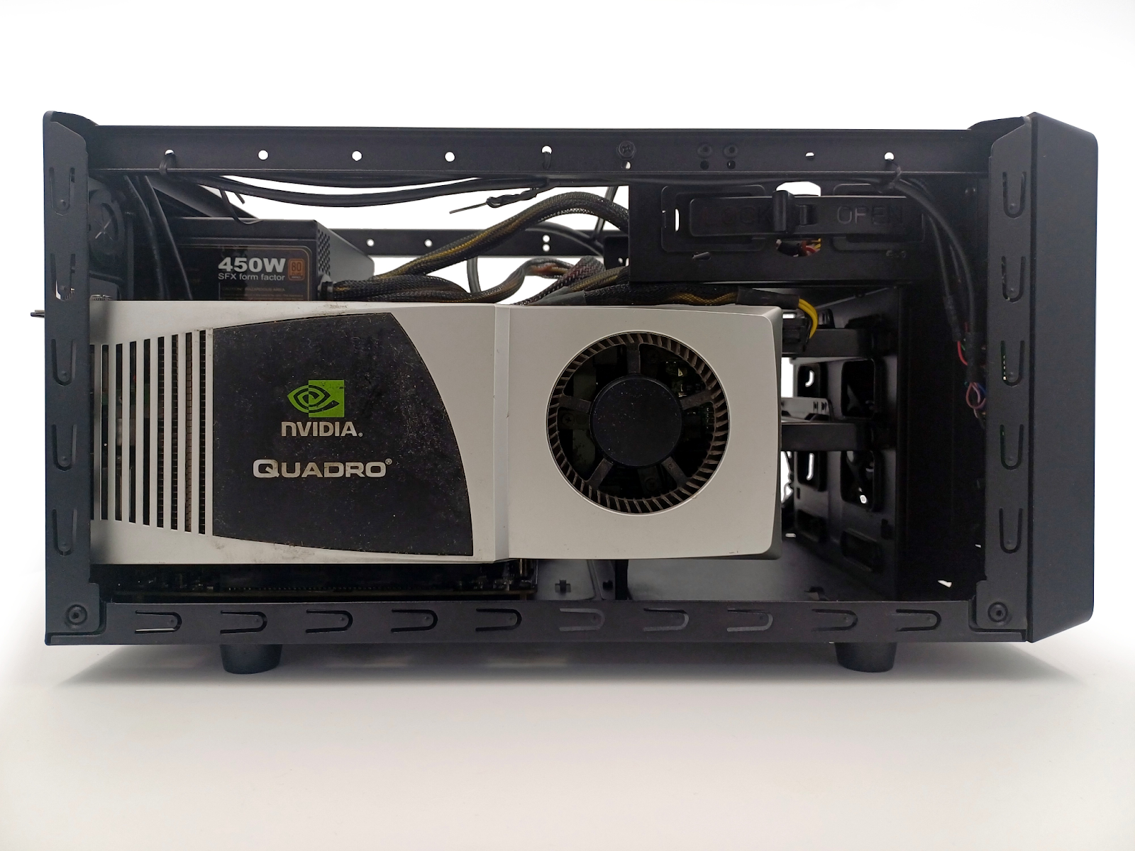
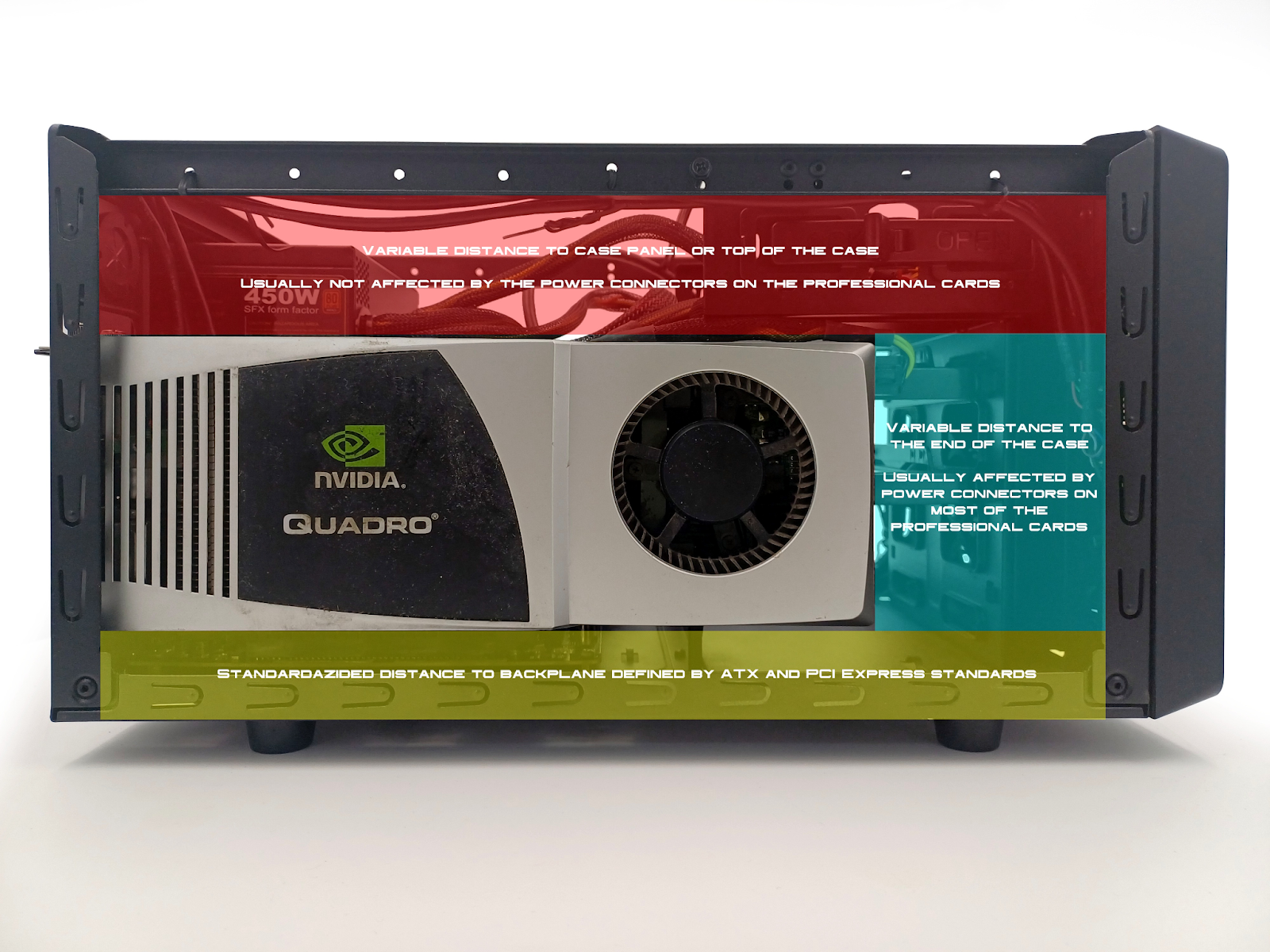
Part of the problem seems to be NVIDIA wanting to separate the use cases of consumer/gamer cards from the ones that can be used in densely packed server systems and workstations since professional Quadro and Tesla cards have power connectors oriented length-wise instead of facing top of the card.
The attempt to separate these markets makes sense—we don’t want crypto miners and AI farms to scalp all the cheaper consumer cards, reducing the availability of the new cards to later flood the second-hand market with cards that may be quickly failing in the gamers’ PCs.
But does it really work? If someone wants to go cheap at a large scale, then he doesn’t necessarily have to use rack solutions or such slim rack cases that he can’t install adapters on top of the card.
Solving this problem through physical design, IF this is actually reasoning behind such physical product segmentation, seems weird for a company that could, if it wanted to, limit such use in a single system through software and drivers not allowing multiple consumer cards running specific types of workloads.
Also, while it makes sense to restrict some types of cards, like blower cards, from getting onto the market by NVIDIA, are open-air cooler design cards really that rackable in densely packed systems, so they are affected by that connector placement restriction as well?
Card partners versus NVIDIA on the connector location
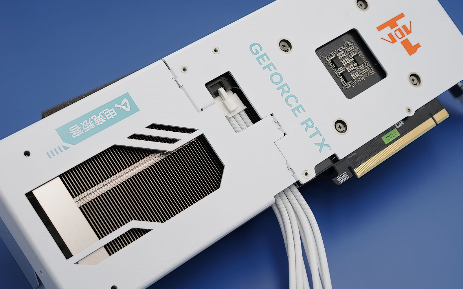
It seems as graphics card manufacturers, so NVIDIA card partners, have their hands tied when it comes to releasing a consumer card with connectors oriented lengthwise at the back of the card. We still get those cards with blower-style cooler designs from time to time, but they are usually really late compared to the rest of the models based on specific NVIDIA chips.
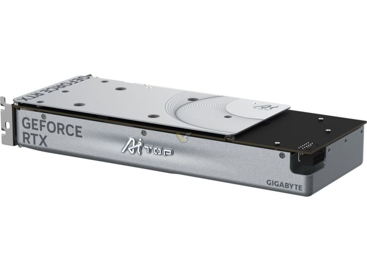
Gigabyte RTX 4070 Ti SUPER AI TOP 16G launched half a year after the RTX 4070 Super Ti launch
Looking back at the stealth cable designs from ASUS, Gigabyte, and Inno3D from the perspective of this problem, it may just be that designers at all those companies are trying to go around the restrictions from NVIDIA, thus ending up with suboptimal solutions.
Whether the solutions being proprietary is caused by ASUS’ attempt at locking us down in their own ecosystem or trying to go around the restrictions on power locations from NVIDIA, we don’t really know.
Should we just wait for things to happen?
Should we stay passive, hoping for new designs to be served, or should we discuss and show those guys in our SFF communities (and general PC hardware communities) what we want and what we would prefer to buy? That’s the only thing that makes sense apart from voting for one of the designs with our wallets.
I assume that there are enthusiasts working at the card vendors that are lurking in our communities looking for ideas but also gathering sources to support their ideas on how to improve things or make a new product, so if we want to push things forward and use the opportunity in front of us, we should be discussing how those cards should look like, how motherboards and PSUs should look like, and so on.
But we’re closest to the change in GPU power connector location since we can see the intent for the change from the card vendors, and we should focus on that first.
Ground rule: the Hippocratic Oath
Looking back at the “let’s unify the X number of standards” problem, we should keep in mind that anything that wants to have a chance of gaining traction needs to be compatible with most of the existing use cases.
It doesn’t need to definitely support every possible-to-support edge case, but if we want the card form factor to survive, it needs to sell well and keep selling well, and for it to happen, it needs to be widely compatible with existing systems.
Only then may card vendors be willing to increase the amount of the cards of the proposed new form factor type if these will be sure to sell over time to clients with various system configurations. If such a card format were to be a niche market, it’ll probably stop making sense for the vendors after some time.
Already the approach ASUS has taken with their stealth power connector design means they are not supporting ITX boards and any other vendors’ boards, and even not all of their boards will support those cards.
Inno3D’s approach, the one in the released 4070 card, doesn’t really deliver on the stealth cable as the cable is sticking out from the top of the card, but more importantly, it’s something that can cause problems in the cases where the card back is against some wall, like with desktop/console style cases.
Doesn’t have to be a silver bullet for all SFF problems, though
At this point you might be thinking, “What about the big beefy cards with multiple cables? Aren’t those the biggest problem for SFF graphics card fitting?” to which I would answer “yes, but actually no.”.
We want to be able to cover the majority of the use cases, but we can’t assume we have to solve all problems at the same time. Cards with multiple power connectors are already so big that changing the connector placement may be meaningless for them as they won’t fit SFF cases anyway.
How can we measure what is the majority of the cards used by the gamers? The answer to that can be found in the steam hardware survey.
After filtering out laptops and integrated GPUs and setting some arbitrary thresholds based on the card TDP, we can see that cards requiring a single external power cable—either PEG 6PIN or 8PIN—are the ones with TDP above 75W, but at most 200W are the majority of the market, adding up to 62% of cards.
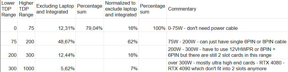
Within the range of 200W to 300W TDP, we get 16% of cards that either use two PEG power cables or a single 12V HPWR cable. There are a lot of 2.5 slot and thicker cards here in current Geforce generations, but there are still some 2 slot cards here.
Cards over 300W TDP are just 7% of the desktop cards—this is the segment where the cards are beefier, with hardly any two slot cards seen here in the current generation.
The thresholds for the groups of cards are arbitrary because they need to be chosen somehow, but the ones that I picked show that a target for a dual slot up-to 300W TDP card is somewhere between 60% and 80%.
This doesn’t mean that those 62% of the cards are just 2 slot cards, but the new design of the card connector placement will (or should) make sense for those cards in context of the remaining 23% of the top-tier cards being potentially too big for the SFF market to matter.
While I was writing this article, AMD announced they’ll focus on the mainstream cards segment to gain users instead of competing in the enthusiast GPU segment:
Determining and removing variables from the equation
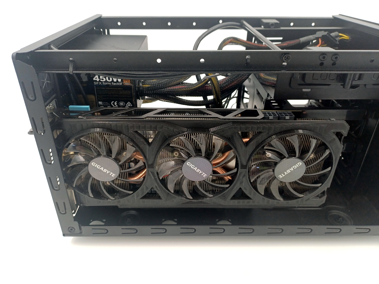
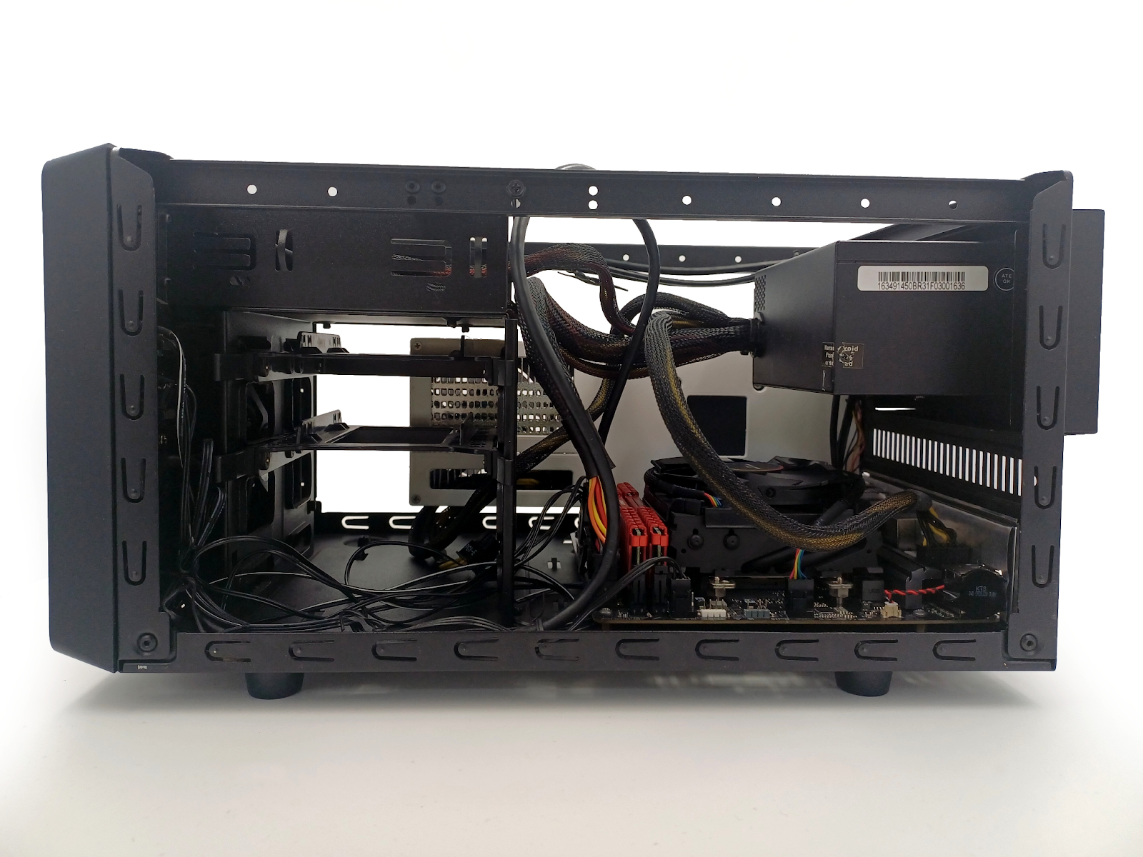
To explain the variable relations in the context of graphics card power connector placement, it’s good to show it off in something combining features of ATX cases and space restrictions of SFF cases.
The old Cooler Master Elite 120 Advanced that I had laying around is a good example of a case like that—it’s effectively as if we cut a tower case in half to have a cross-section showing us the placement of the GPU against the motherboard backplane thanks to the fully open sides when the cover panel is removed.
It’s worth noting that Inno3D’s design is perfectly utilizing the gap between motherboard and drive cage for the cable routing, so for this style of cases, this seems like a win for Inno3D’s design team.
A PCI Express specification reference-sized graphics card will have the power connectors placed within the reference card area, meaning that the case designers could predict how much space is needed for the power connectors and cables.
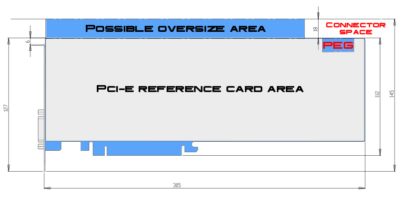
Note that the length of the card on the drawing is not defined by the PCI Express specification
In this specific chassis, power connector placement on the card is important because PCI-E power cable connectors can get directly underneath the edge of the 5.25 drive bay structure.
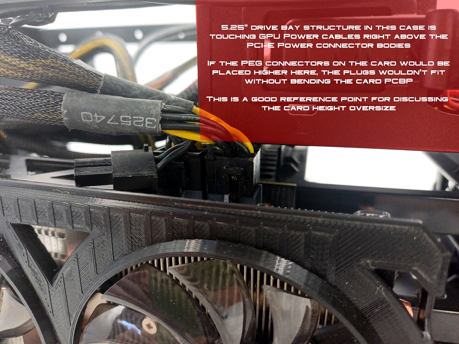
While newer cases of this style probably wouldn’t allow this kind of situation, this is a good reference point for discussing the card height oversize and the power connector placement.
If this card was any taller here, the plugs wouldn’t fit underneath the 5.25” drive bay structure. If the power connectors were placed closer to the rear of the case, however, this wouldn’t be a problem anymore.
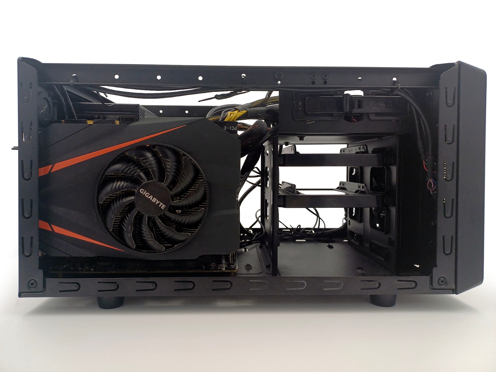
Many ITX-sized cards (length up to around 170mm) have taller PCBs, and the power connectors are placed higher because of that.
In the case of this Gigabyte 1080 Mini, the power connector on the card is recessed so the cable connector fits in the outline of the card, but still the cables are not fitting in this outline. Also, it’s not recessed to the area of the PCI Express specification reference card, so the connector wouldn’t fit underneath the 5.25” drive bay structure if the card was significantly longer with the connector at its end.
If the chassis was made to fit a card of specific height + required additional height for the cables to fit, and the consumer is presented with a taller card that uses this additional space to fit a higher-end chip or better cooling, but at the same time shifts the placement of the power connector, it’s not possible to determine the fit just based on the dimensions of the card without information on where the connector is placed.
Because the power connector placement is not a part of the requirements for the cards to be accepted as compliant with the PCI-E standard (as if placing it incorrectly meant the card wouldn’t get a certificate that is required for it to work with motherboards), the connector placement is all over the place in oversized cards.
If placing a connector facing up on the card makes so much mess, how about orienting it horizontally as in professional cards? Wouldn’t it solve this problem?
Well, not really—by changing the connector orientation but sticking to the same rules, we are just shifting the problem to the length of the card, where for tower cases it may not matter, but for SFF ones it definitely does.
In this situation, however, it’s kind of hard to determine where would be the reference placement of the connector card-lengthwise—how much it should be recessed from the end of the card? Does being recessed determine the cable not needing to go outside and route around the card?
If we want to squeeze the card fitting tightly front-to-back in a case that has some kind of separation wall or a drive cage right behind the card, then the routing of the cable behind the card may be obstructed.
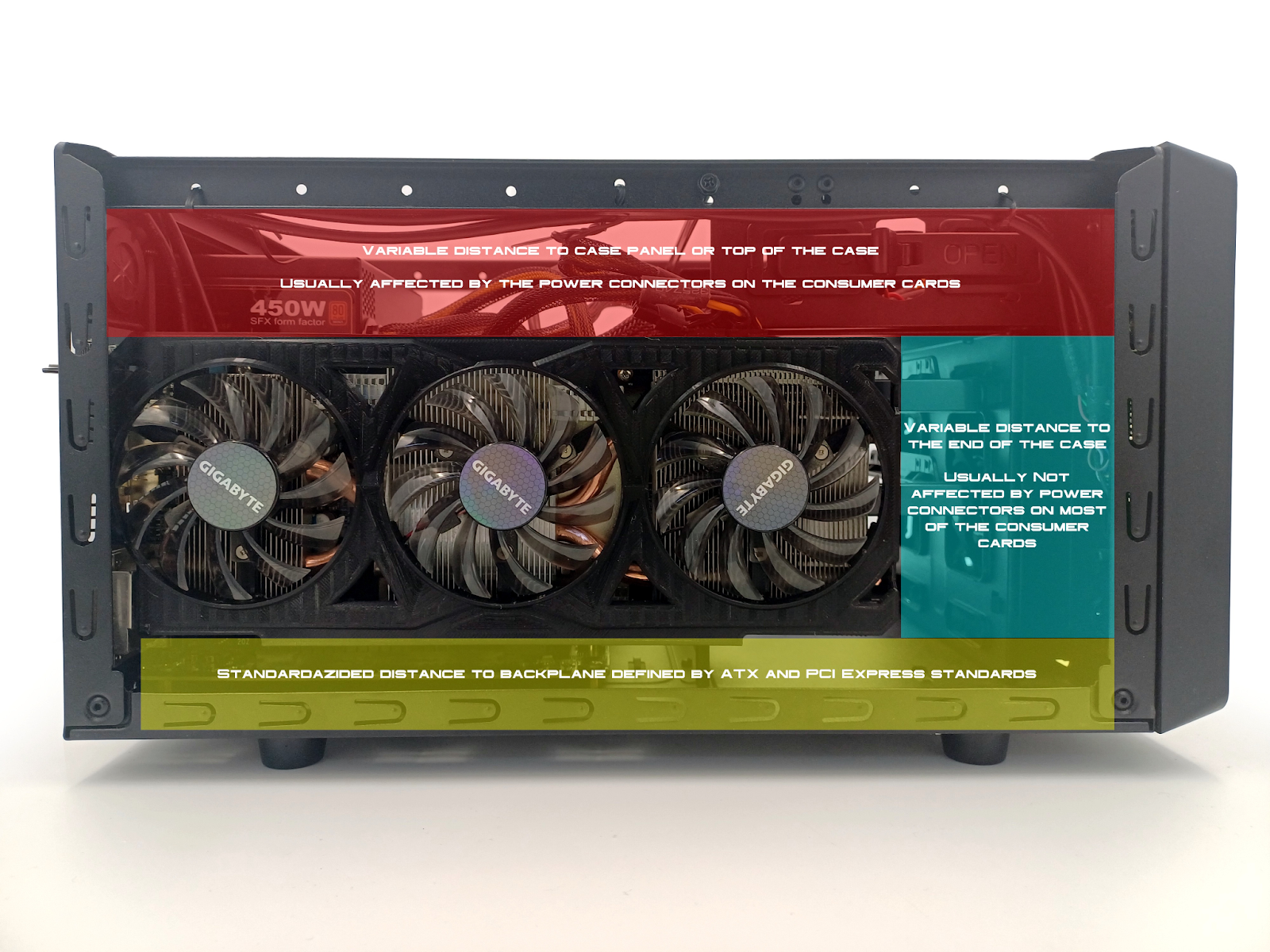
Note that in both situations of consumer and professional card connector placement we always have that space below the card, which is defined by PCI Express standard and ATX standard—how much away is the card main body from the motherboard and how much away is the motherboard for the metal backplane? This space is something that doesn’t change much except for the cases not having a motherboard backplane throughout the whole case but just behind the motherboard.
If we want to simplify this problem by removing the possible variables, then avoiding going up and to the side means going down where we are mostly sure what we’ll encounter.
This also means that height and length will be the only requirements for fitting the card in context of space for it in the GPU compartment without the need to figure out how much space for the cable is required.
Visualizing the desired card by referencing existing design
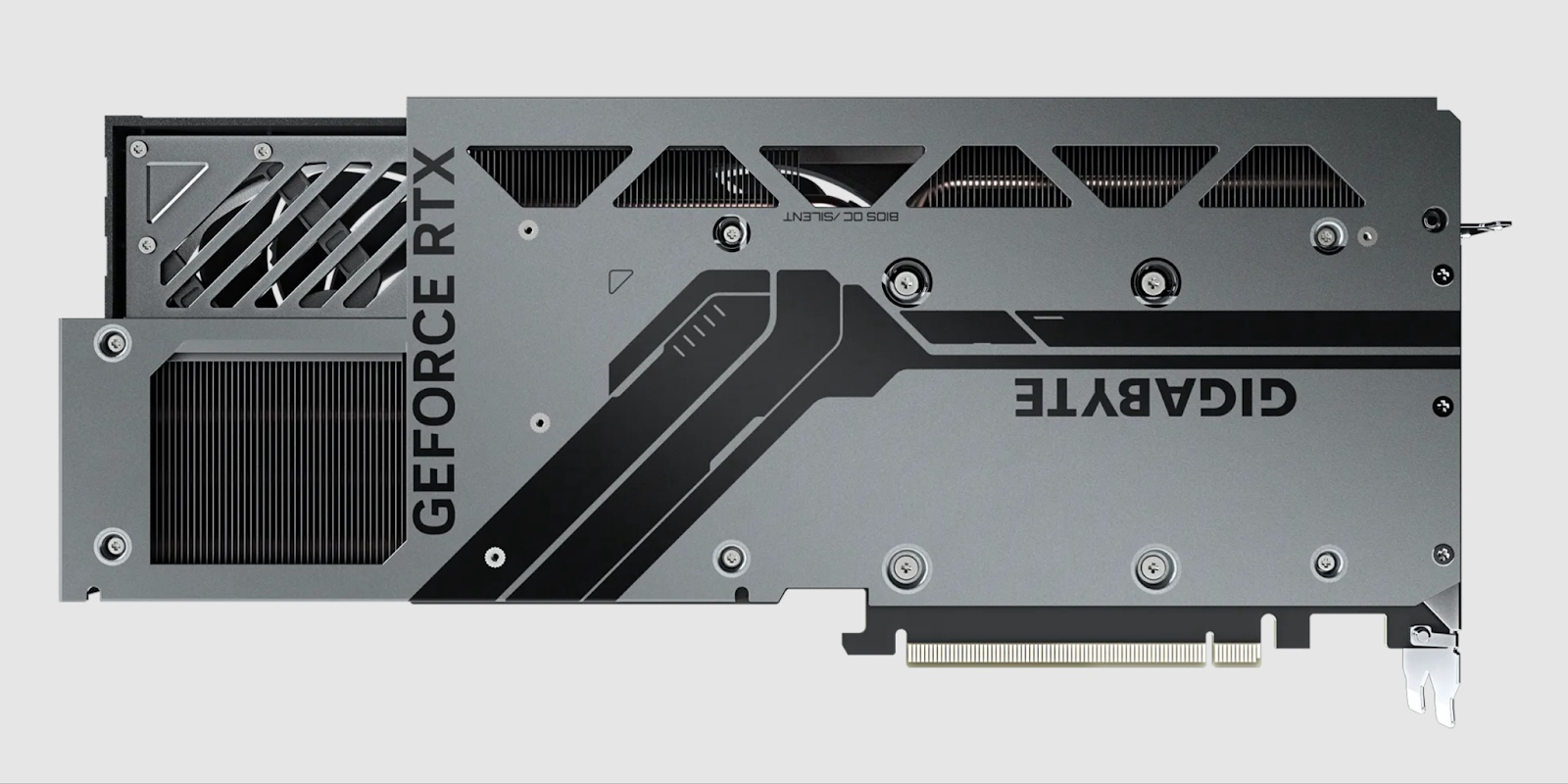
Because of the 12VHWPR connector bend issue, there are cards that have a really big recess for the power cable like this one: Gigabyte GeForce RTX™ 4070 Ti SUPER WINDFORCE MAX OC 16G
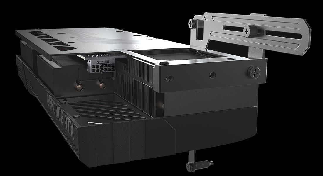
The recess, however, is on the top of the card, on the far side from the PCI-E connector, so in the context of cases having a separation wall right behind the card or horizontally placing this card for a console/desktop layout, it means the cable would still need to be routed somewhere around the card.
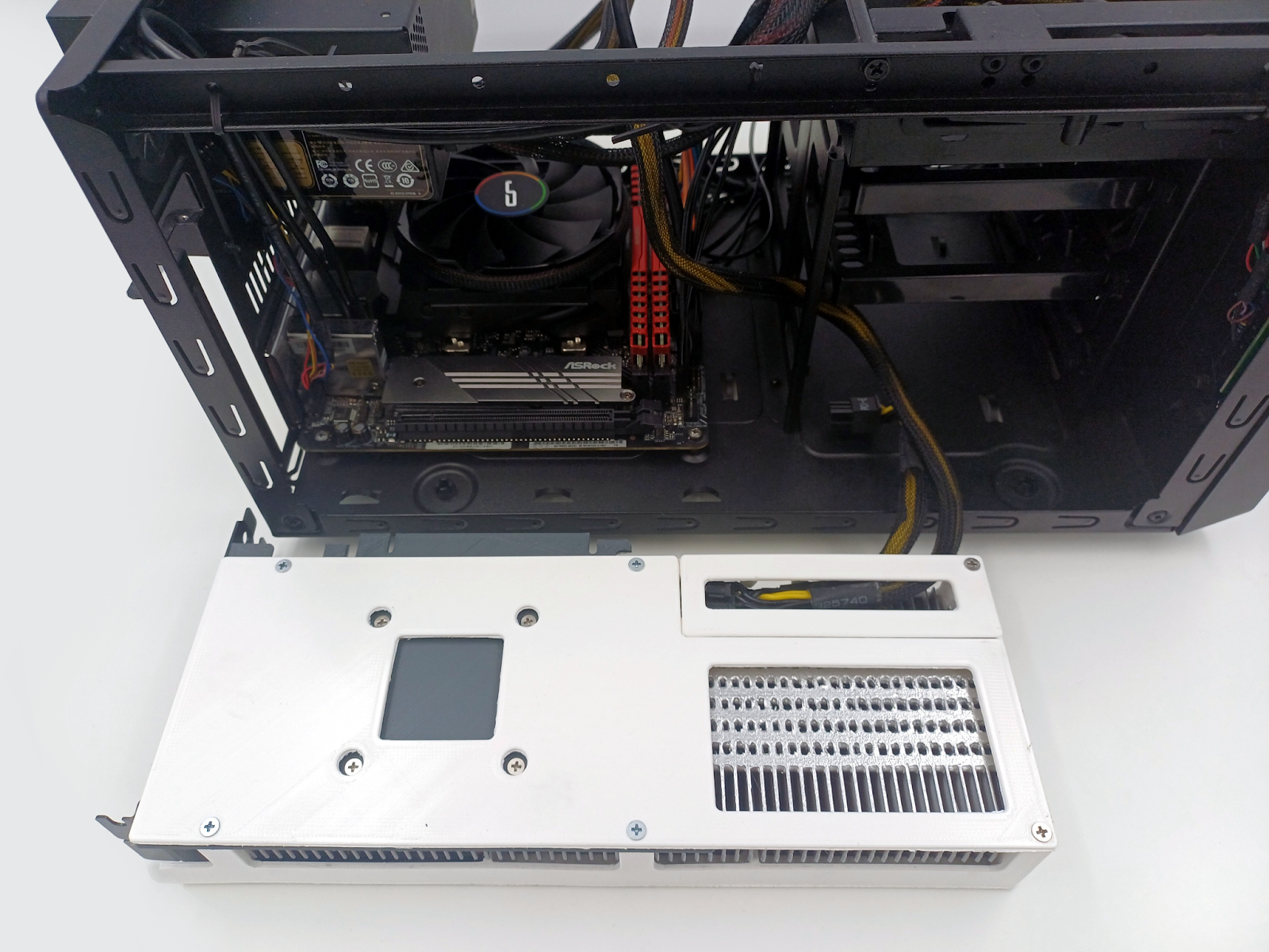
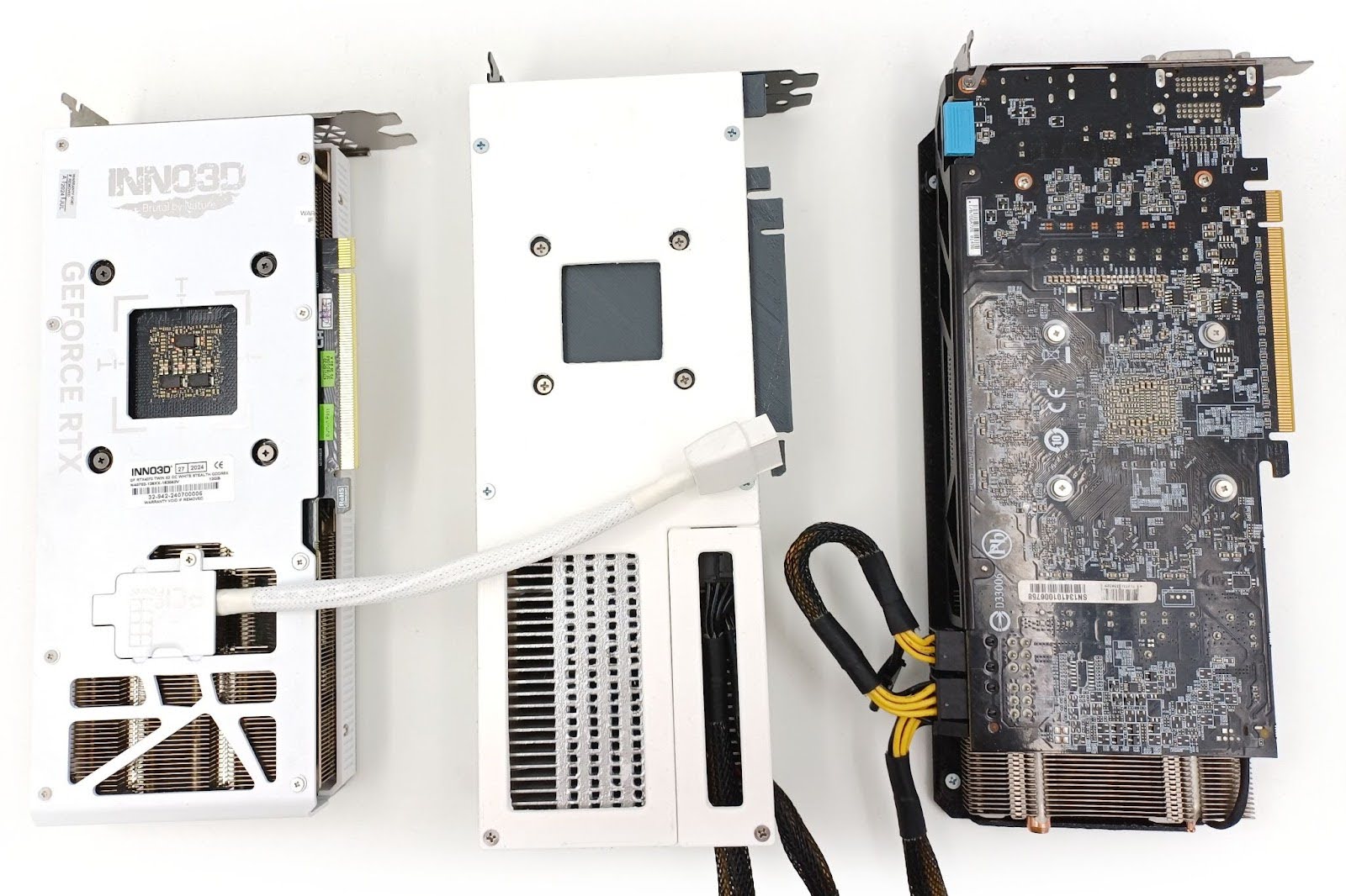
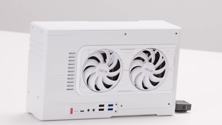
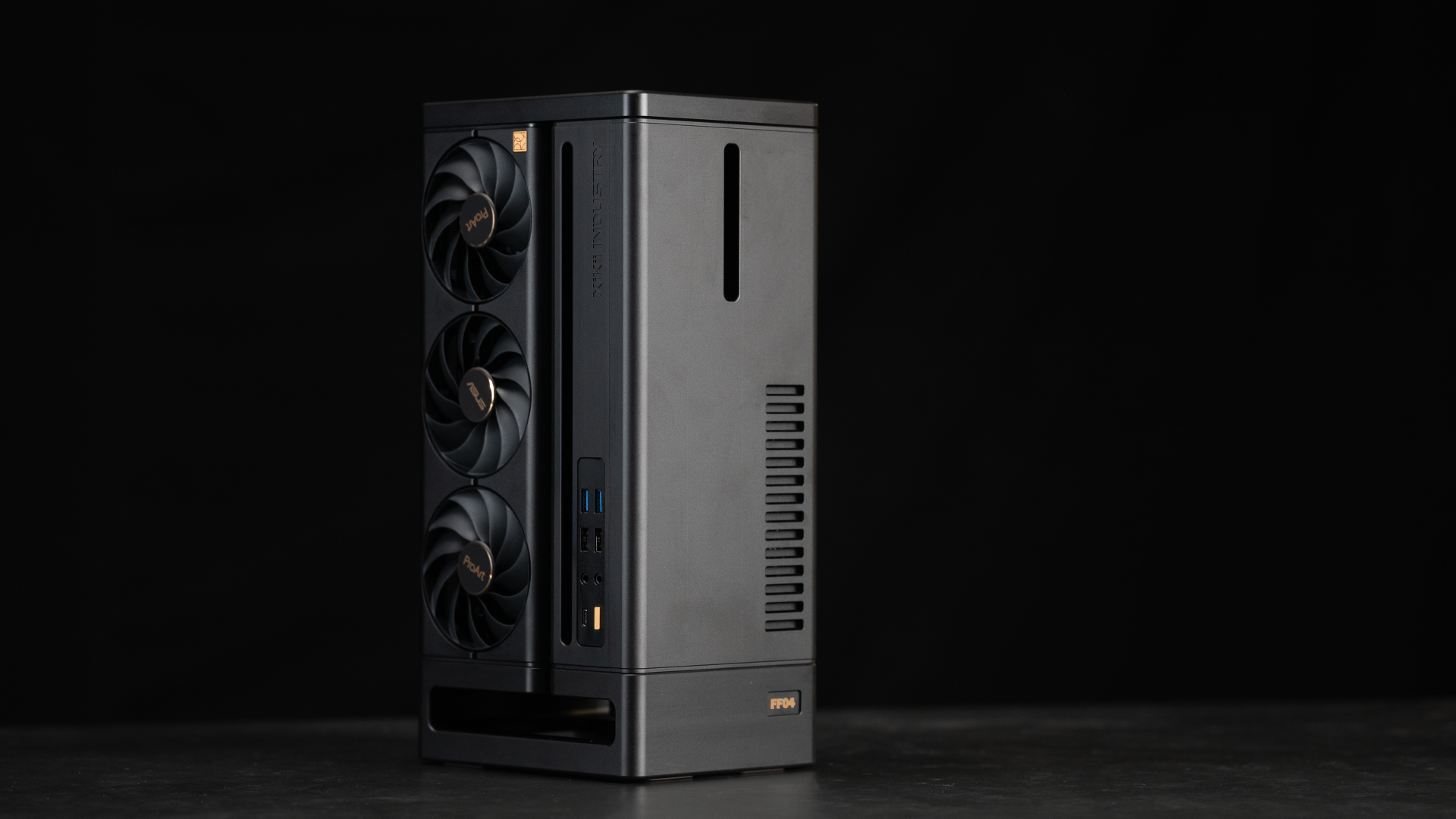
So what we would want to do is to go from this:
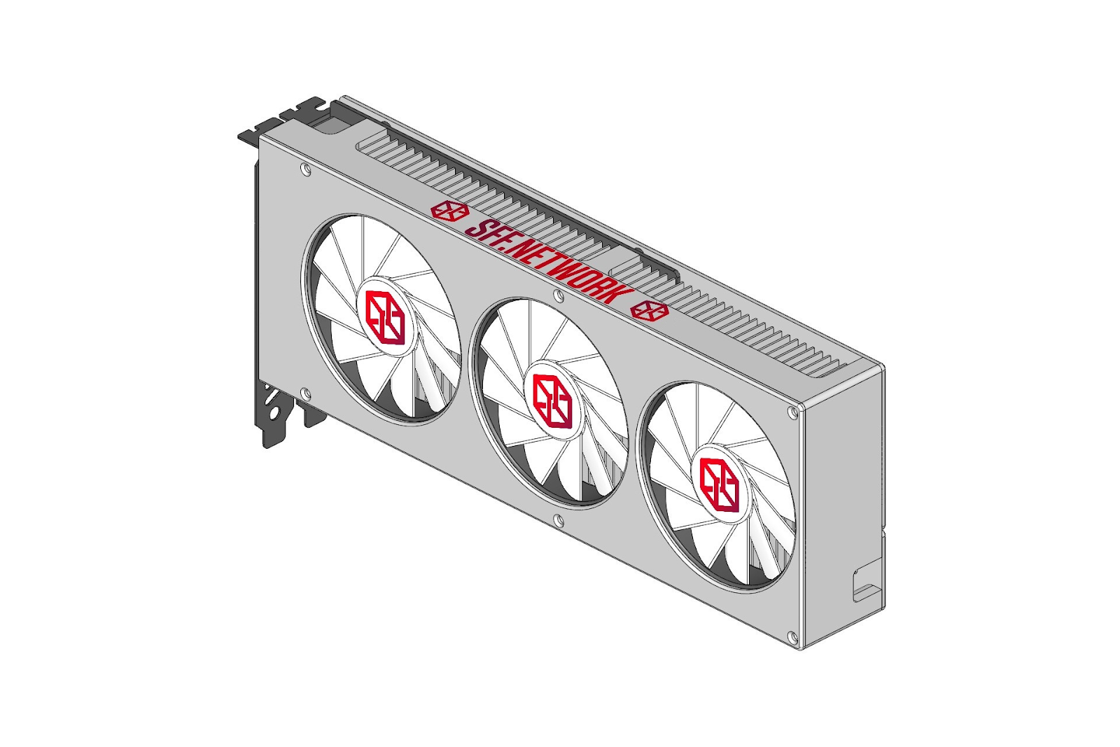
to something like this (a photo mock-up):
This kind of design would allow us to go down while having a reasonable amount of space for the cable bend of 12VHPWR. The existence of this card and stealth designs having connectors on the bottom of the card (Asus and Gigabyte) means it is doable, but still it doesn’t exist yet—we don’t have it physically yet.
If it looks stupid but it works, it ain’t stupid.
Both when it comes to testing if something makes sense and convincing others that it makes sense, the closer to the real thing you get, the better.
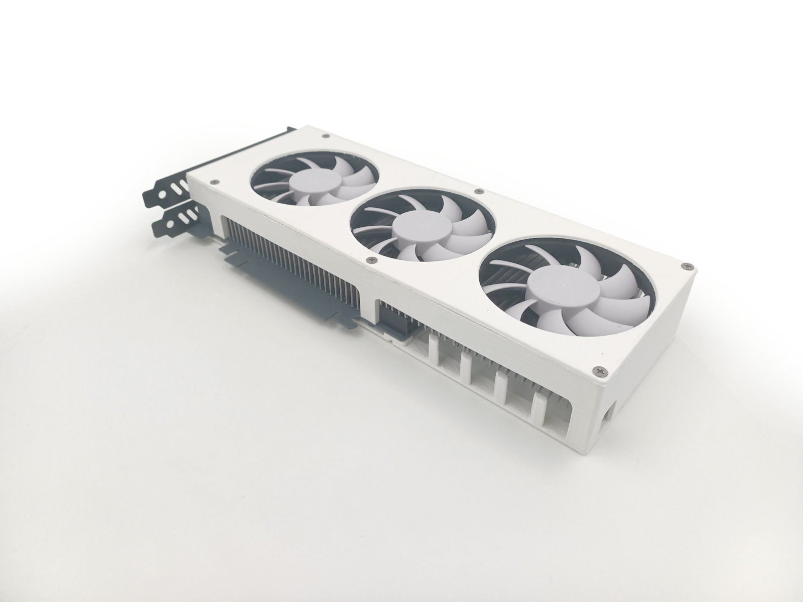
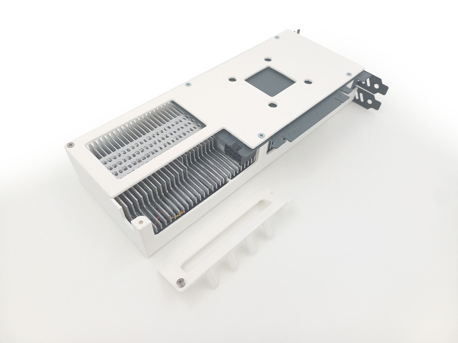
Of course we can’t make our own card prototypes that would actually work, but it doesn’t mean for discussing the problems we need actually working cards—we can mock-up things, modify existing cards by soldering cable adapters to place the connector at a different spot, and even 3D print something to test and convey your idea closer to the real thing.
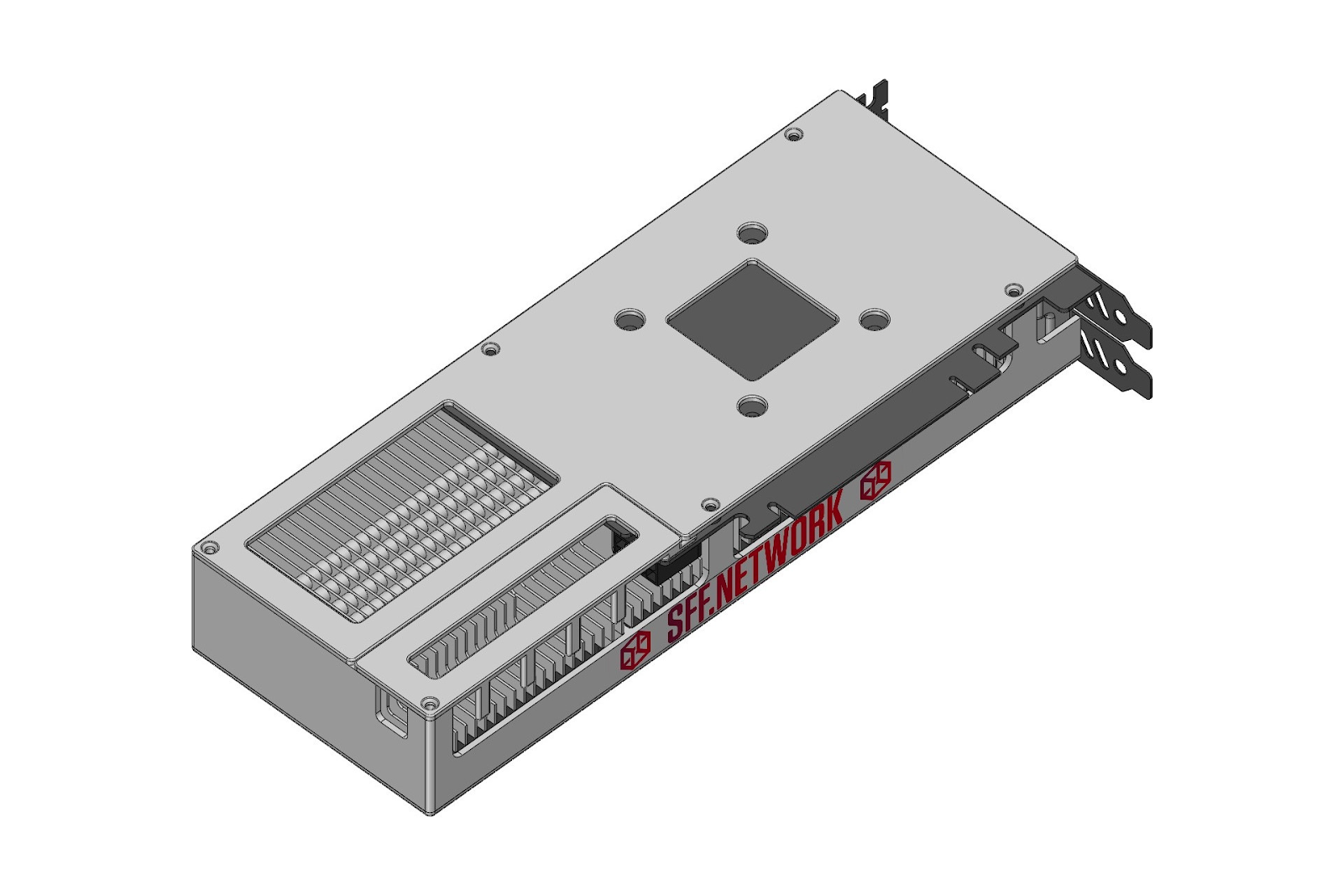
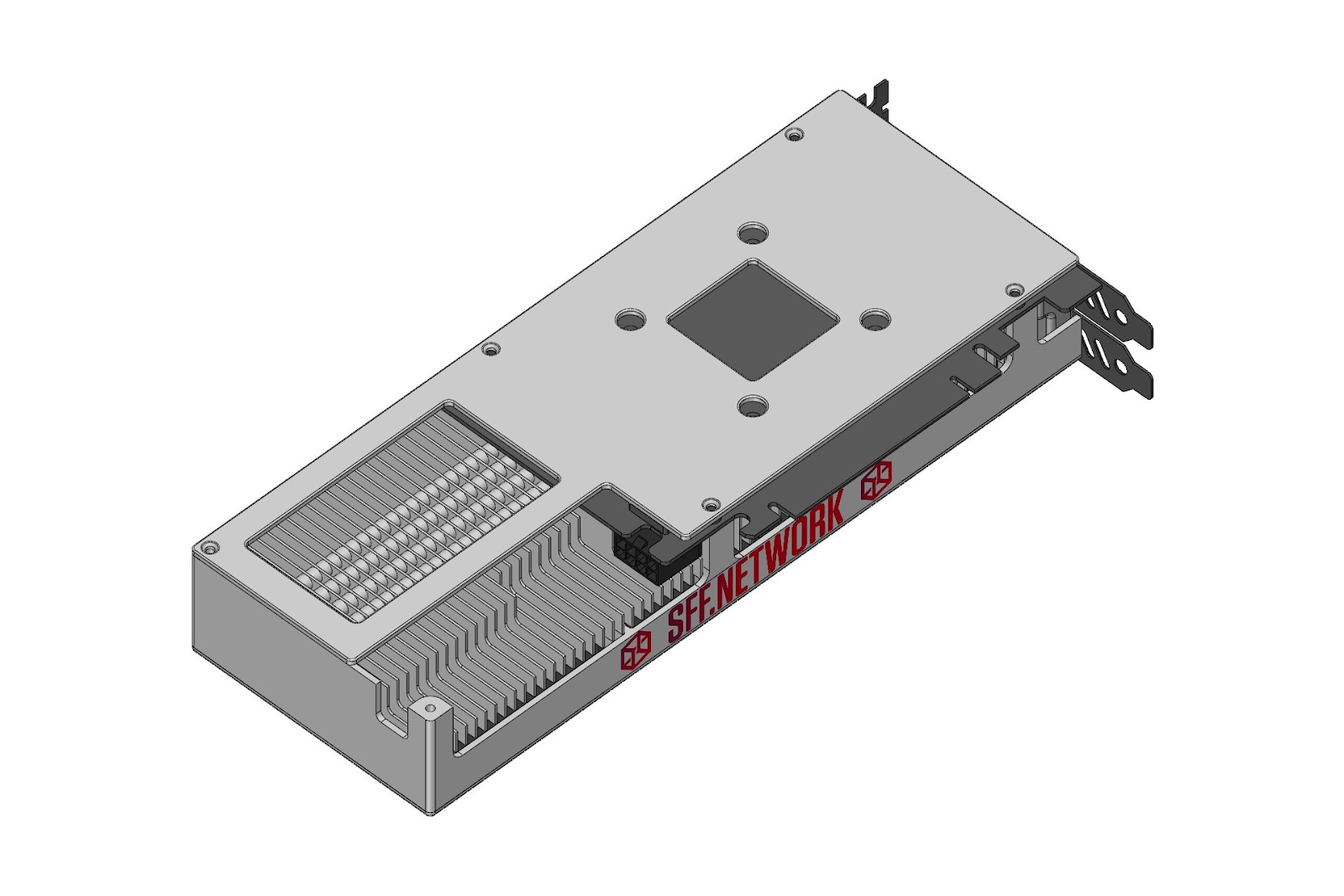
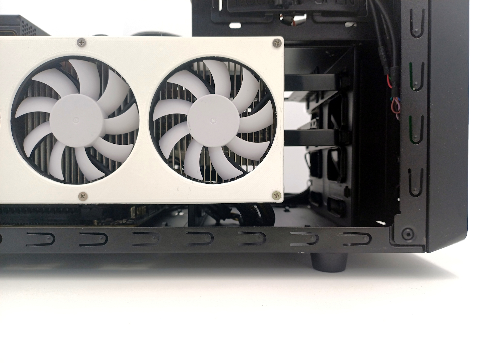
What I did was 3D printing a mock-up of a graphics card to test my idea and discuss it with others:
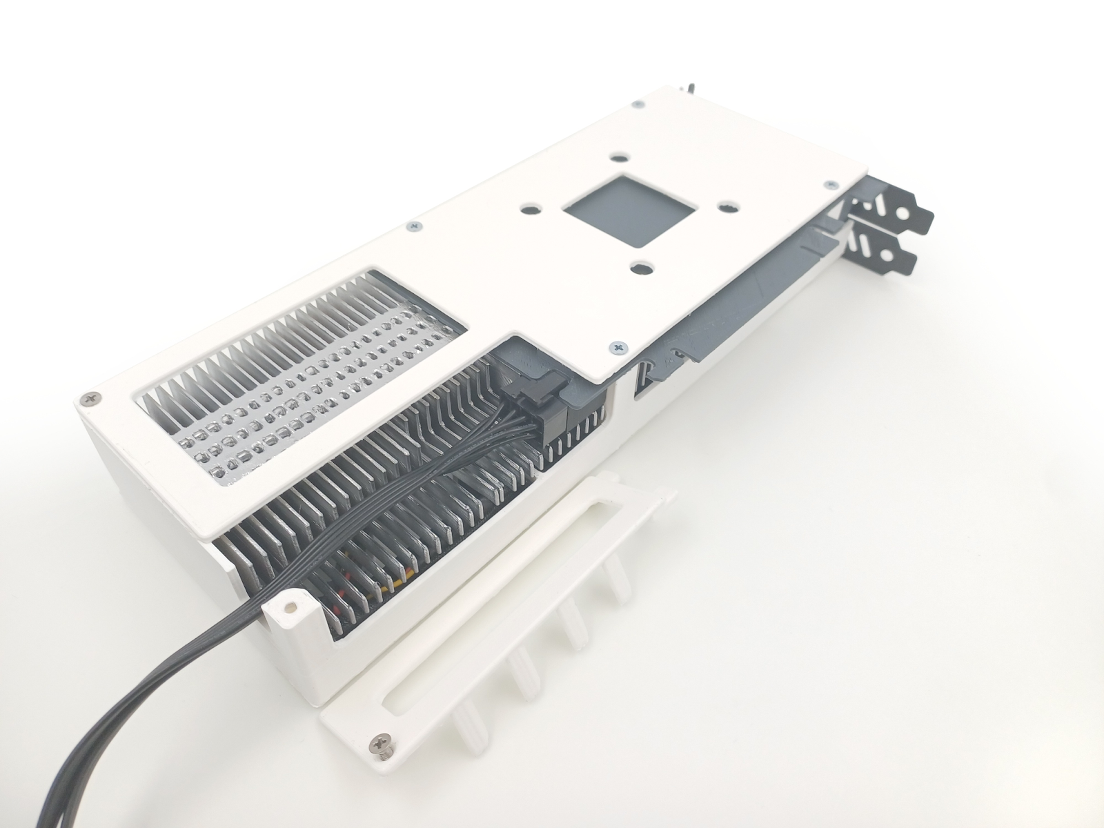
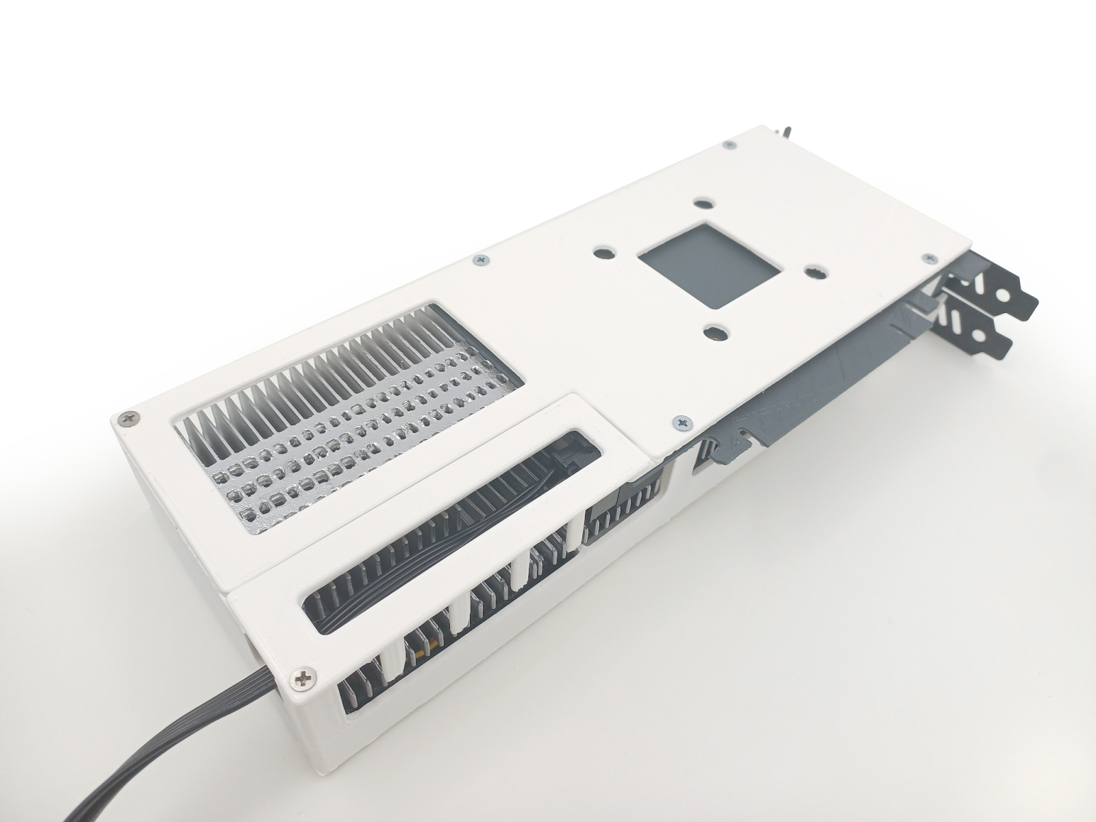
ASUS’ and Inno3D’s designs are telling us that something like this is plausible, and they already tackled some of the problems along the way. ASUS’s proprietary connector card shows that if the vendors want, they can move the power connector to the bottom of the PCB. Inno3D’s design shows that it’s acceptable, at least for the PEG 8 PIN cable, to be potentially touching the radiator fins and be in the stream of air passing through it.
I think this connector placement and orientation might be the best solution for both SFF builds and full ATX clean no-cable builds.
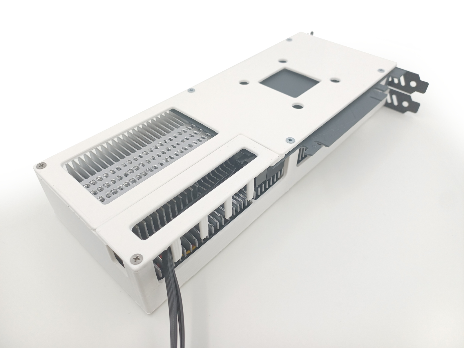
Allowing for the cable to run along the length of the card means we can bend it at different distances from the connector depending on the motherboard size and where we want to route the cable to.

Note that thanks to the 10.5”/267mm card being longer than the ATX motherboard width of 244mm, the cable can go out of the card at the bottom before the card’s end, avoiding collision with the motherboard while still maintaining the assumption that the cable isn’t supposed to take part in dimensions calculation.
Actual stealth cable feature with ATX and mATX boards
Handling of the actual stealth cable feature with ATX and mATX motherboards would work like this:
It would work the same with the mocked-up Gigabyte card from above; a cable organizer is not necessary.
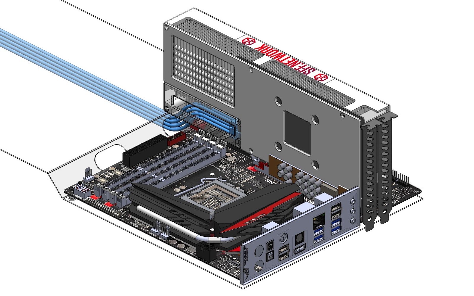
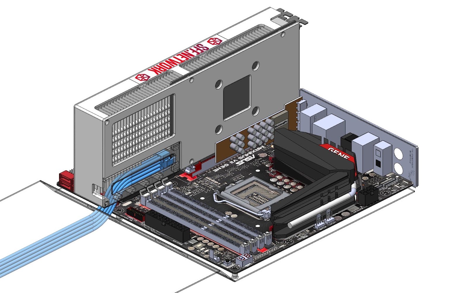
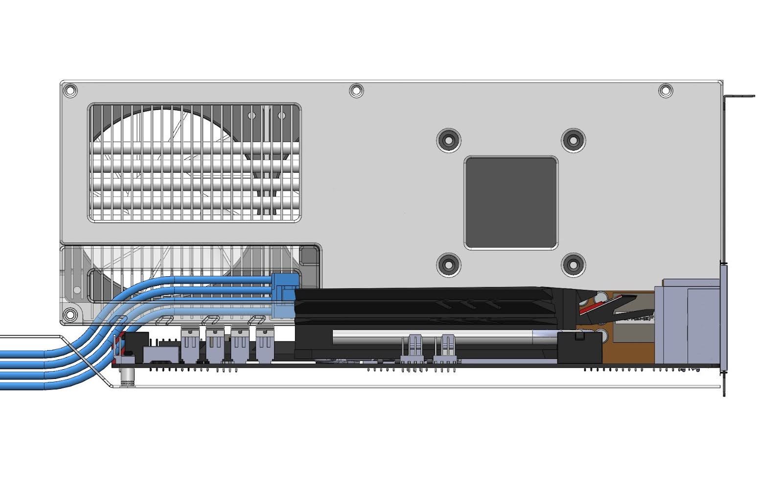
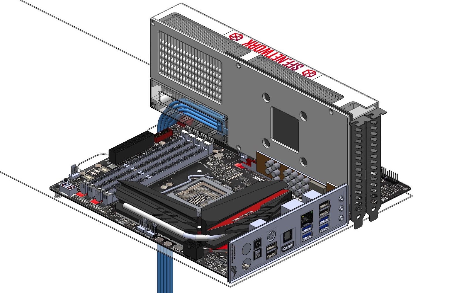
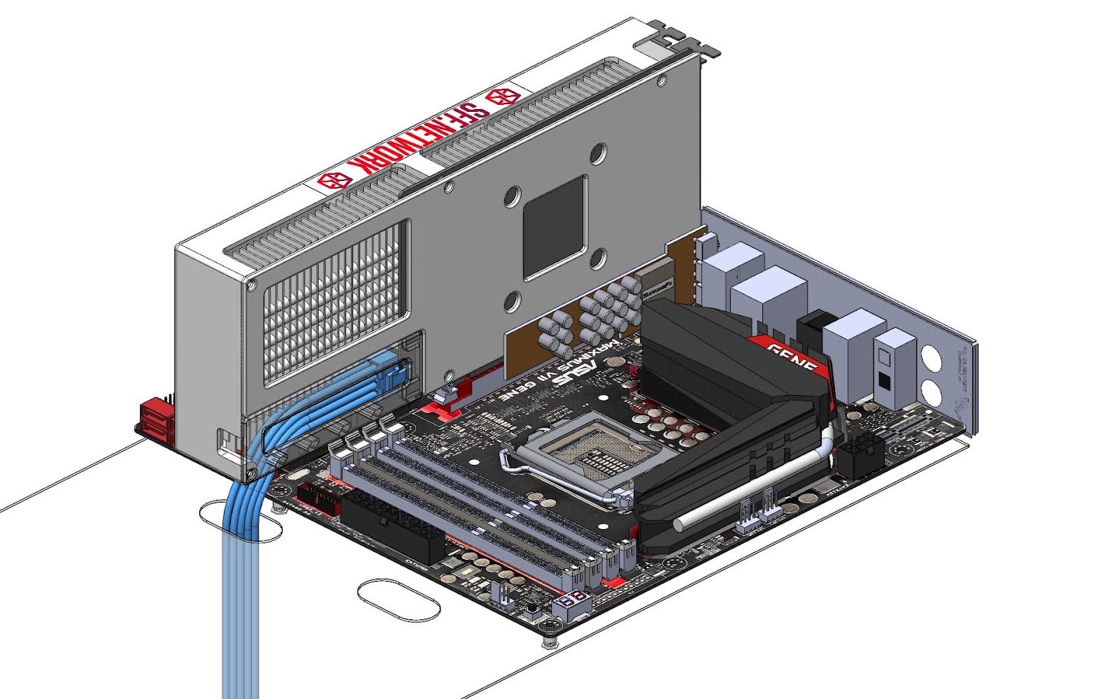
Credit to Yang Ji for Asus Maximus VII Gene mATX motherboard model on GrabCAD https://grabcad.com/library/asus-maximus-vii-gene-micro-atx-motherboard-z97-lga1150-1
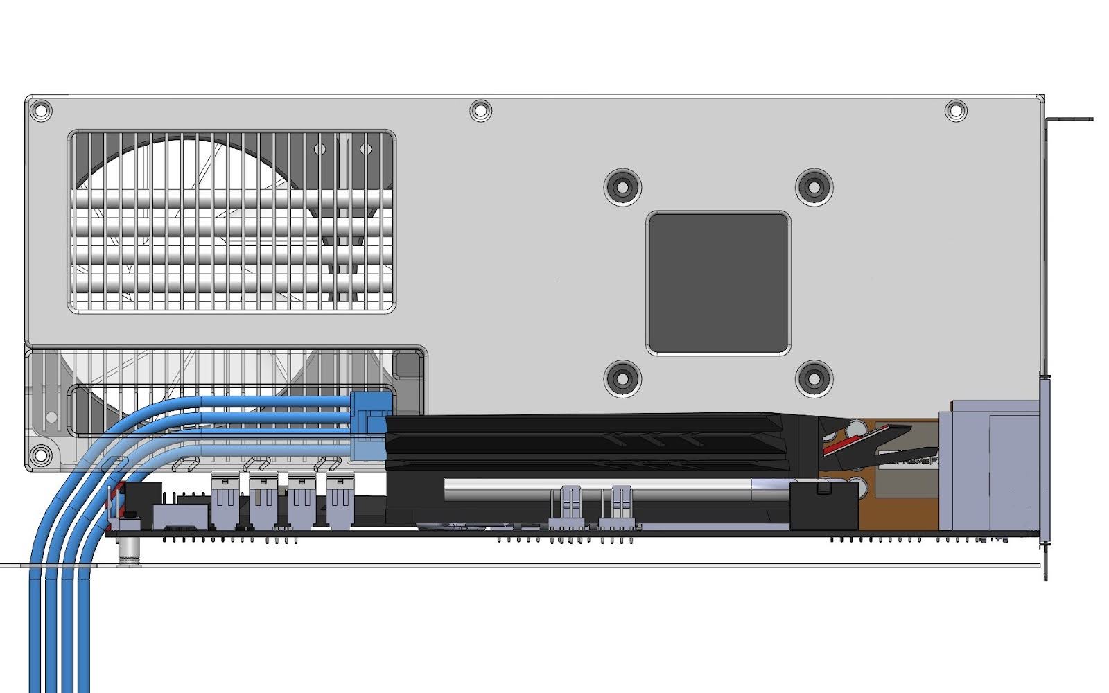
Potential support of stealth cable for GPU vertical mounts
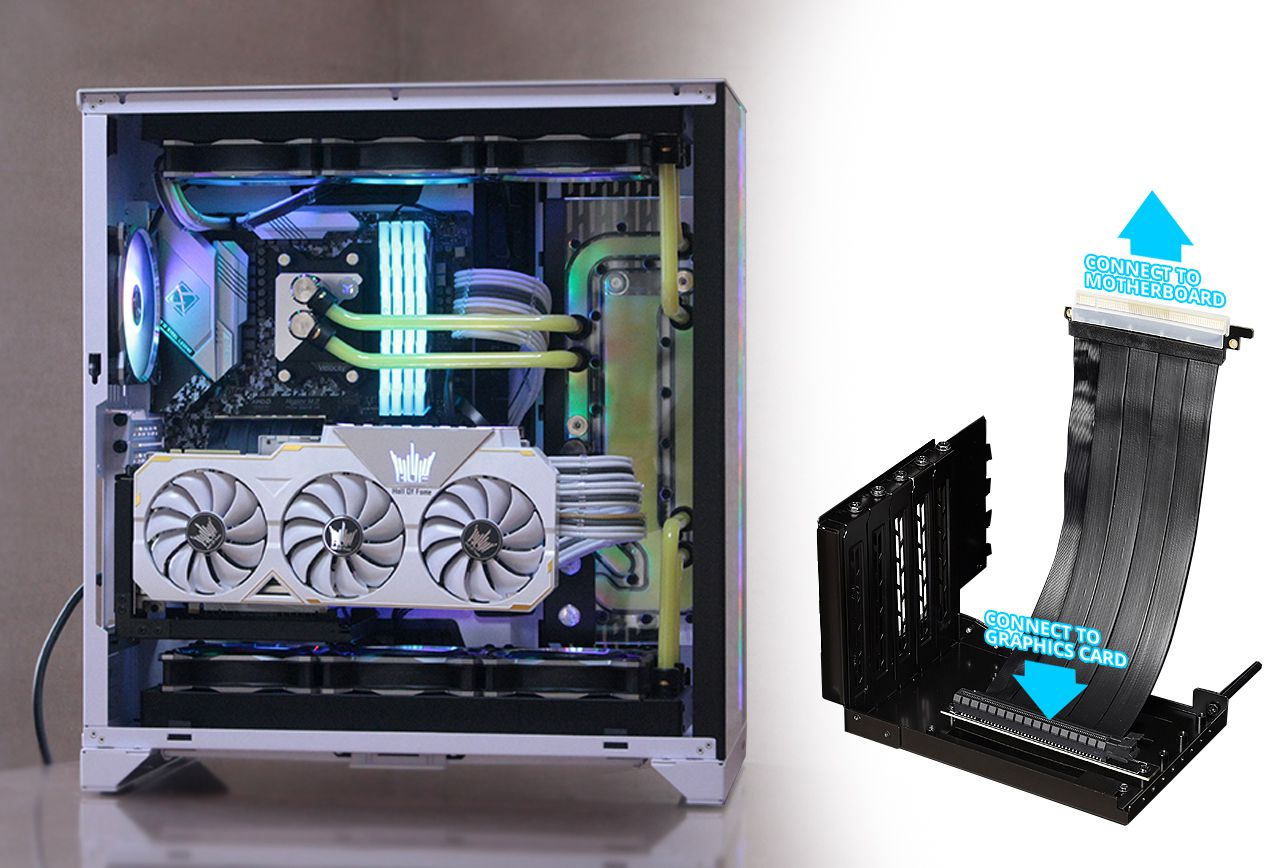
Depending on the design of the cable cover, it may be possible to also let the cable out through the backplate surface, which can hide the cable behind the card in GPU vertical mount configurations, or simply route the cable down into the power supply compartment.
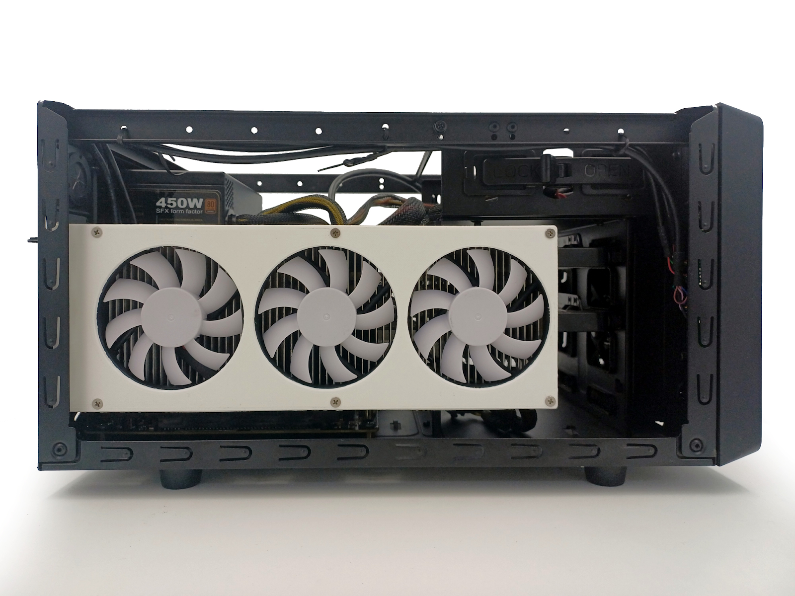
Physical testing in the case
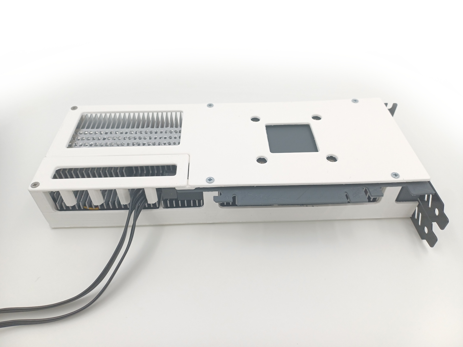
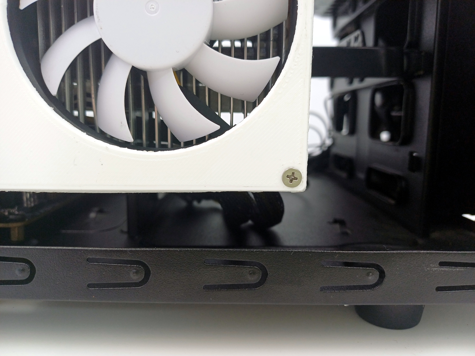
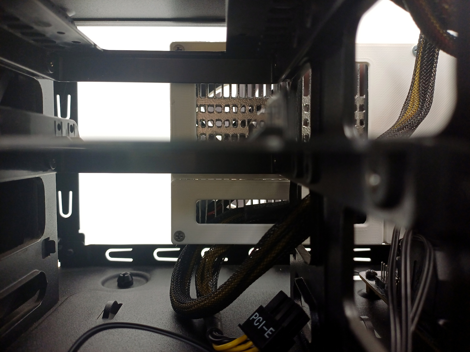
Before announcing a great success, however, let’s see how it works in a case that has a motherboard backplane right below the card, in context of the Hippocratic Oath or not hurting the common ATX setup.
It’s worth to note that this kind of design means connecting the cable to the card first before it’s placed in the PCI-E slot. It’s not really worse, it’s just different—current PSUs should have enough slack to handle this, but if you want to manage the cables by tying them up to something, you will have to remember to untie them before removing the card, or in the case of custom extra-short modular cables, to unplug them from the PSU to remove the card.
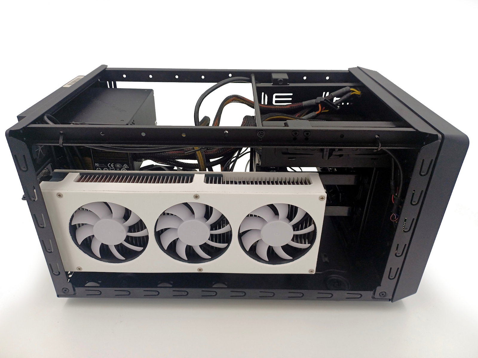
Looking at the cable routing from the other side shows that the cable has enough space to bend between the card and the motherboard backplane/floor of the case here.
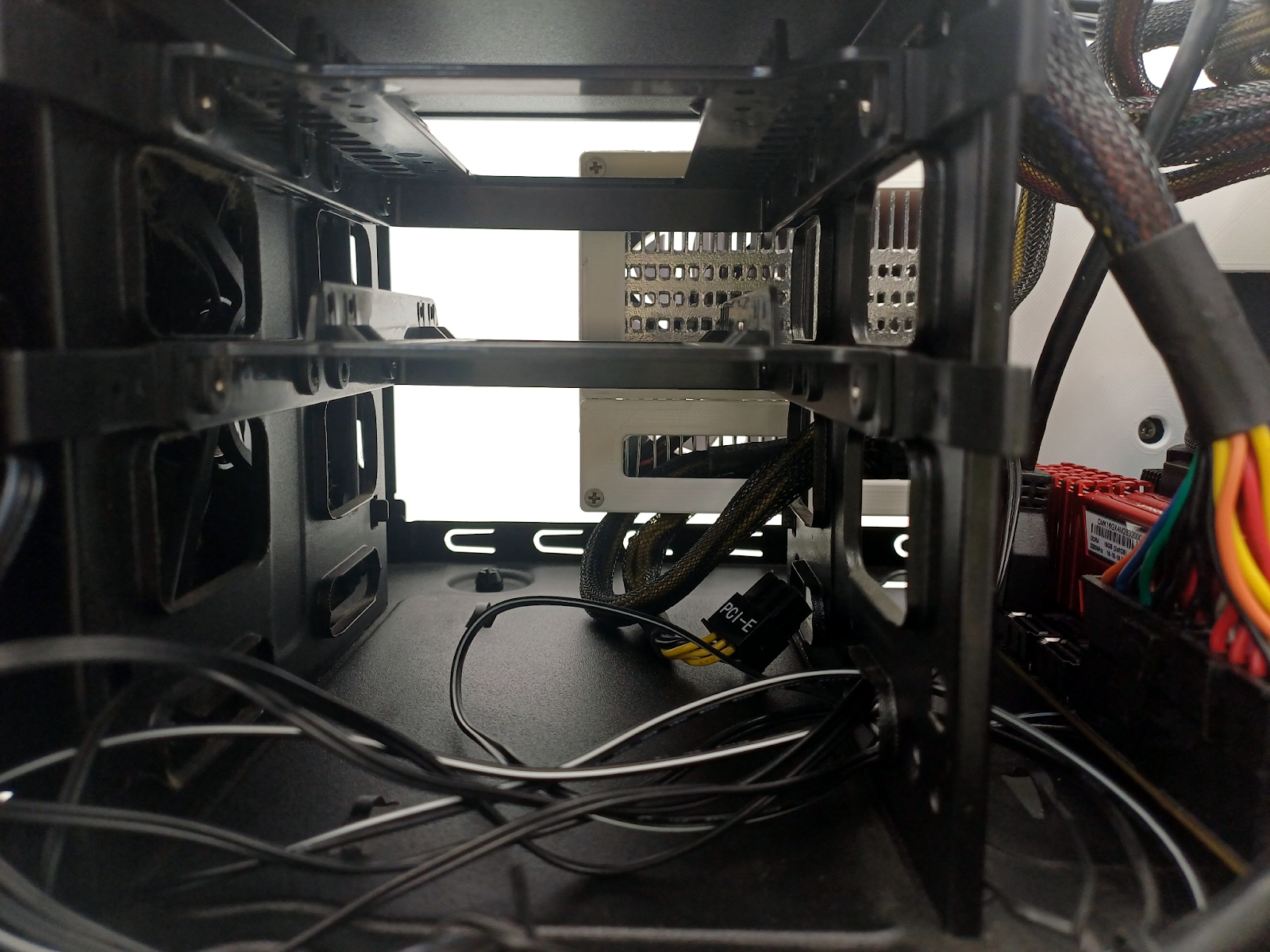
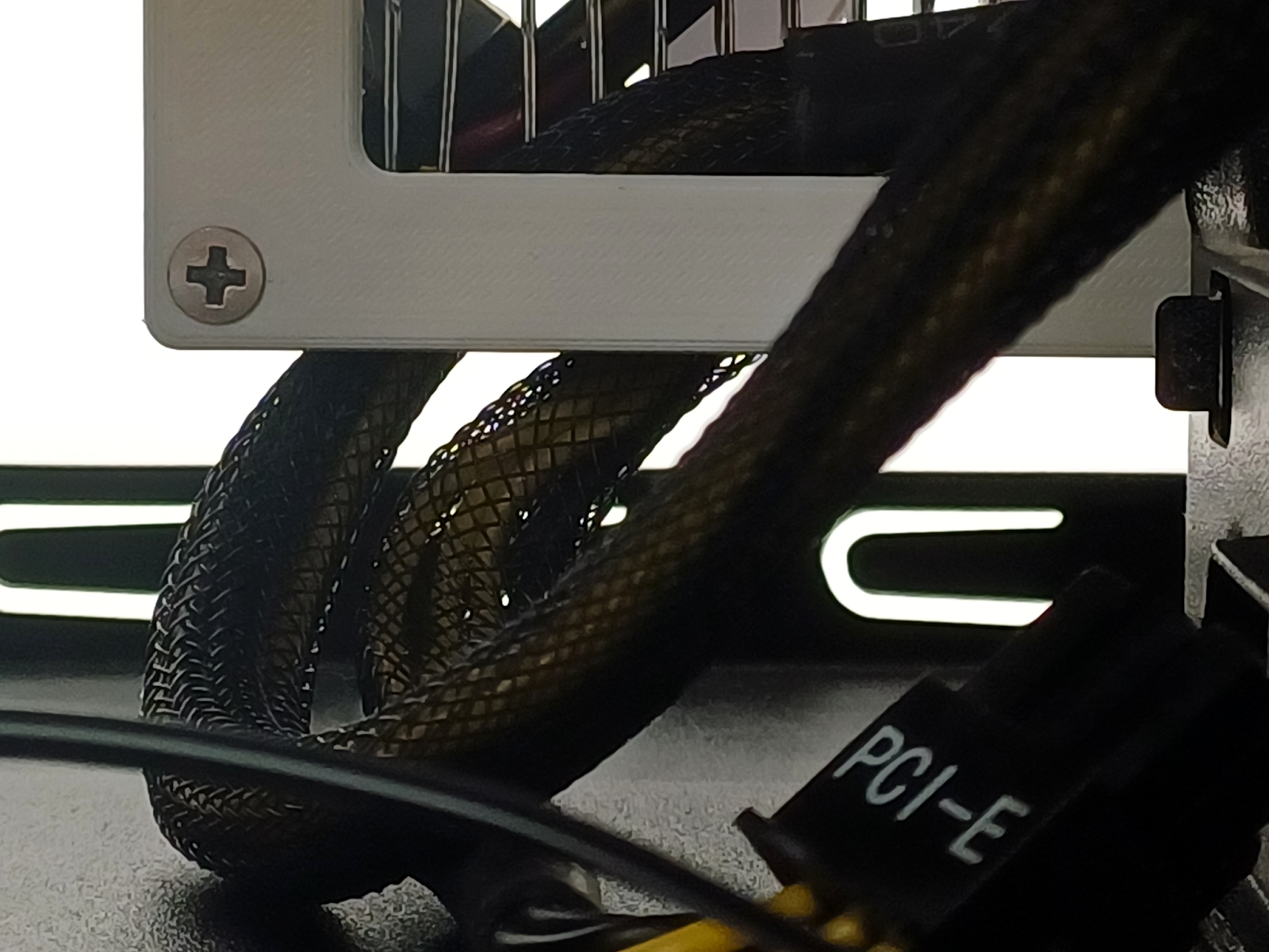
Note, however, that this concept model is forcing the cable to come out at a specific spot and direction; leaving just an open cut-out on the card could mean an easier bend for such a scenario just by not attaching the connector cover to the card.
I could keep showing off various test cases here, but I hope at this point in the article you have a general idea of why this kind of design should be better for our SFF builds, so I will stop here because this article is getting a bit too long already.
Let’s figure this out together
It doesn’t mean, however, that the design shown here is perfect. It’s just an example of how we can test and verify some of our ideas when it comes to fitting and ergonomics of PC component installation. It’s also not a silver bullet solving all the issues of SFF graphics card fitting, especially when it comes to those big high-end cards we are seeing on the market.
So think about what you would do differently. Discuss it, draw your idea, and show it to others. If you have a 3D printer, maybe print your own idea or check someone else’s idea to help them. If you’re a content creator or just tinkering making 3D printed cases all the time, maybe consider making a mock-up build that doesn’t necessarily fully work but shows how such a system could look like. Or maybe you know about a card that would be a perfect base for the mod where we can solder the connector and attach it in a different spot with some kind of 3D-printed bracket?
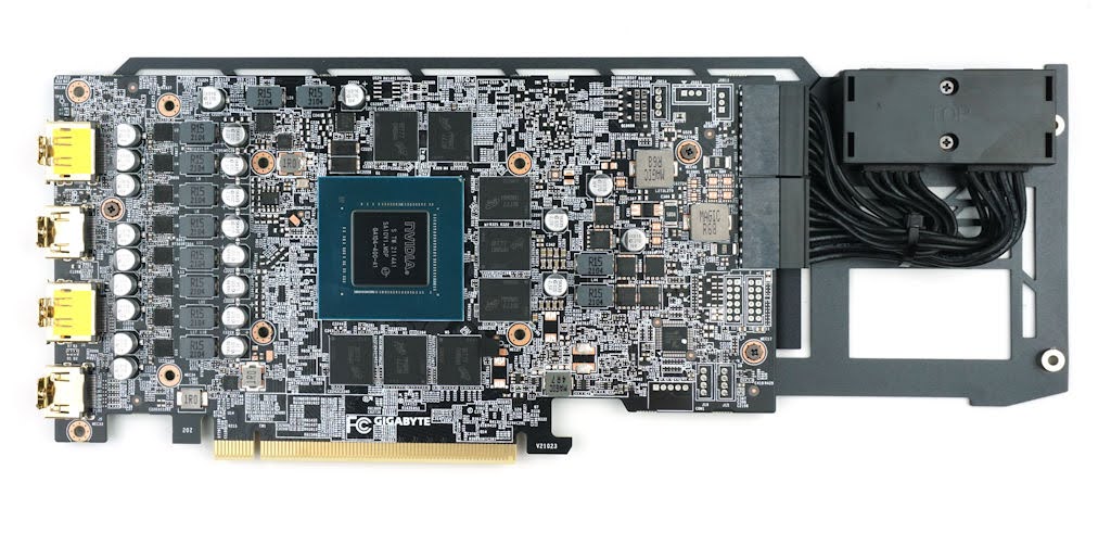
Gigabyte’s RTX 3070 Eagle cards could allow some rerouting of the power connectors as long as the radiator would allow it (may need shaving off some of it for modding)
After all, nothing will bring us closer to having cards that we want until we actually can prove in numbers what kind of designs we want, and if those don’t exist on the market to buy and show that through our wallets, we need to focus on the next best thing, which is either bringing attention of those industry professionals lurking in the shadows to some of the mocked-up concepts and discussions, or voting with our wallets for the designs that makes sense for our builds like the featured Inno3D RTX 4070 card.
